


❏
5. Hold the control horn on the rudder, making sure the
holes align with the hinge gap. The horn must also rest on
the plywood plate installed in the rudder. Use the control
horn as a template to drill 3/32" [2.5mm] holes in the rudder
for the mounting screws.
❏
6. Screw the #4 x 5/8" self-tapping screws into the holes.
Remove the screws, and apply three drops of thin CA to
each hole drilled to harden the underlying plywood. Re-attach
the control horns using the #4 x 5/8" self-tapping screws.
❏
7. Thread a 4-40 hex nut and a 4-40 clevis onto the
threaded end of the pushrod wire. Attach the clevis to the
control horn.
❏
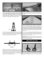
8. Use a felt-tip pen to mark the pushrod wire where it
crosses the holes in the aileron servo arm. Cut the pushrod
wire 3/4" [19mm] behind the mark.
❏
9. Locate a solder clevis. Use the following sequence to
solder the clevis to the pushrod:
❏
A. Lightly sand the pushrod and clean it with alcohol.
❏
B. Insert the pushrod into the non-threaded clevis. The wire
should protrude 1/16" [1.5mm] inside the forks of the clevis.
❏
C. Apply a small amount of soldering flux to the joint.
❏
D. Apply heat evenly to the pushrod and the clevis and
then touch the solder to the joint and allow it to flow.
❏
E. Allow the pushrod and clevis to cool slowly before
continuing.
❏
10. Place a clevis retainer onto both of the clevises.
Attach the pushrod to the servo and control horn.
❏
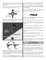
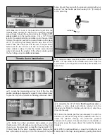
1. Locate the
tail gear assembly.
Position the assembly
so the bend is 1/8" [3mm] in front of the hinge line on the
rudder. Mark the fuselage where the gear assembly will
enter the fuselage. Drill the location using a 9/64" [3.5mm]
drill bit.
❏
2. Attach the tail gear to the fuselage using two
nylon
landing gear straps
and four
#2 x1/2" sheet metal screws.
❏
3. Thread a
nylon clevis
14 turns onto a
2-56 x 12"
pushrod wire
. Slide a clevis retainer onto the clevis and
attach the clevis to the tail wheel steering arm.
❏
4. Install a brass
screw-lock pushrod connector
on the
rudder servo horn. Snap the
nylon retainer
onto the
pushrod connector post beneath the servo horn.
RETAINER
Tail Gear Installation
INCORRECT
CORRECT
HINGE LINE
17


