


APPENDIX
FLIGHT TRIMMING
Note:
The following article has been reprinted in part for future reference
and also as a guide for your flight instructor or experienced flying partner to
help you with trimming your model. If further information is required, please
contact your local hobby dealer, local flying club or call Great Planes at
(217) 398-8970
A model is not a static object. Unlike a car, which you can only hunt left
or right on the road (technically, a car does yaw in corners, and pitches
when the brakes are applied), a plane moves through that fluid we call air
in all directions simultaneously. The plane may look like it’s going forward,
but it could also be yawing slightly, slipping a little and simultaneously
climbing or diving a bit! The controls interact. Yaw can be a rudder problem,
a lateral balance problem or an aileron rigging problem. We must make
many flights, with minor changes between each, to isolate and finally
correct the problem.
The chart accompanying this article is intended to serve as a handy field
reference when trimming your model. Laminate it in plastic and keep it in
you flight box. You just might have need to consult it at the next contest!
The chart is somewhat self-explanatory, but we will briefly run through the
salient points.
First, we are assuming that the model has been C.G. balanced
according to the manufacturer’s directions. There’s nothing sacred about
that spot — frankly, it only reflects the balance point where a prototype
model handled the way the guy who designed it thought it should. If your
model’s wing has a degree more or less of incidence, then the whole
balance formula is incorrect for you. But, it’s a good ballpark place to start.
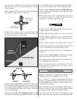
The second assumption is that the model has been balanced laterally.
Wrap a strong string or monofilament around the prop shaft behind the
spinner, then tie the other end to the tail wheel or to a screw driven into the
bottom of the aft fuse. Make the string into a bridle harness and suspend
the entire model inverted (yes, with the wing on!). If the right wing always
drops, sink some screws or lead into the left wing tip, etc. You may be
surprised to find out how much lead is needed.
At this point the model is statically trimmed. It’s only a starting point, so
don’t be surprised if you wind up changing it all. One other critical feature
is that the ailerons must have their hinge gap sealed. If shoving some
Scotch tape or Monokote into the hinge gap to prevent the air from slipping
from the top of the wing to the bottom, and vice-versa, bothers you, then
don’t do it.
To achieve the maximum lateral trim on the model, the hinge gap on the
ailerons should be sealed. The easiest way to do this is to disconnect the
aileron linkages, and fold the ailerons as far over the top of the wing as
possible (assuming they are top or center hinged). Apply a strip of clear
tape along the joint line. When the aileron is returned to neutral, the tape
will be invisible, and the gap will be effectively sealed. Depending on how
big the ailerons are, and how large a gaping gap you normally leave when
you install hinges, you could experience a 20 percent increase in aileron
control response just by this simple measure.
Your first flights should be to as certain control centering and control feel.
Does the elevator always come back to neutral after a 180° turn or Split-S?
Do the ailerons tend to hunt a little after a rolling maneuver? Put the plane
through its paces. Control centering is either a mechanical thing (binding
servos, stiff linkages, etc.), an electronic thing (bad servo resolution or dead
band in the radio system), or C.G. (aft Center of Gravity will make the plane
wander a bit). The last possibility will be obvious, but don’t continue the
testing until you have isolated the problem and corrected it.
Let’s get down to the task of trimming the model. Use the tachometer
every time you start the engine, to insure consistent results. These trim
flights must be done in calm weather. Any wind will only make the model
weather vane. Each “maneuver” on the list assumes that you will enter it
dead straight-and-level. The wings must be perfectly flat, or else the
maneuver will not be correct and you’ll get a wrong interpretation. That’s
where your observer comes in. Instruct him to be especially watchful of the
wings as you enter the maneuvers.
Do all maneuvers at full throttle. The only deviation from this is if the
plane will routinely be flown through maneuvers at a different power setting.
Let’s commence with the “engine thrust angle” on the chart. Note that
the observations you make can also be caused by the C.G., so be prepared
to change both to see which gives the desired result. Set up a straight-and-
level pass. The model should be almost hands-off. Without touching any
other control on the transmitter, suddenly chop the throttle. Did the nose
drop? When you add power again, did the nose pitch up a bit? If so, you
need some down thrust, or nose weight. When the thrust is correct, the
model should continue along the same flight path for at least a dozen plane
lengths before gravity starts to naturally bring it down.
Do each maneuver several times, to make sure that you are getting a
proper diagnosis. Often, a gust, an accidental nudge on the controls, or just
a poor maneuver entry can mislead you. The thrust adjustments are a real
pain to make. On most models, it means taking the engine out, adding
shims, then reassembling the whole thing. Don’t take shortcuts.
Don’t try to proceed with the other adjustments until you have the thrust
line and/or C.G. correct. They are the basis upon which all other trim
settings are made.
Also, while you have landed, take the time to crank the clevises until the
transmitter trims are at neutral. Don’t leave the airplane so that the
transmitter has some odd-ball combination of trim settings. One bump of
the transmitter and you have lost everything. The trim must be repeatable,
and the only sure way to do this is to always start with the transmitter
control trims at the middle.
The next maneuver is somewhat more tricky than it looks. To verify C.G.,
we roll the model up to a 45° bank, then take our hands off the controls.
The model should go a reasonable distance with the fuse at an even keel.
If the nose pitches down, remove some nose weight, and the opposite if the
nose pitches up. The trick is to use only the ailerons to get the model up at
a 45° bank. We almost automatically start feeding in elevator, but that’s a
no-no. Do the bank in both directions, just to make sure that you are getting
an accurate reading of the longitudinal balance.
We now want to test the correct alignment of both sides of the elevator
(even if they aren’t split, like a Pattern ship’s, they can still be warped or
twisted). Yaw and lateral balance will also come into play here, so be
patient and eliminate the variables, one-by-one. The maneuver is a simple
loop, but it must be entered with the wings perfectly level. Position the
maneuver so that your assistant can observe it end-on. Always loop into the
wind. Do several loops, and see if the same symptom persists. Note if the
model loses heading on the front or back side of the loop. If you lose it on
the way up, it’s probably an aileron problem, while a lose of heading on the
way back down is most likely a rudder situation.
Note that the Yaw test is the same looping sequences. Here, however,
we are altering rudder and ailerons, instead of the elevator halves. We
must repeat that many airplanes just will not achieve adequate lateral trim
without sealing the hinge gaps shut. The larger you make the loops (to a
point), the more discernable the errors will be.
The Lateral Balance test has us pulling those loops very tightly. Pull
straight up into a vertical and watch which wing drops. A true vertical is hard
to do, so make sure that your assistant is observing from another vantage
point. Note that the engine torque will affect the vertical fall off, as will
rudder errors. Even though we balance the wing statically before leaving for
the field, we are now trimming it dynamically.
The Aileron Coupling (or rigging), is also tested by doing Hammerheads
Stalls. This time, however, we want to observe the side view of the model.
Does the plane want to tuck under a bit? If so, then try trimming the ailerons
down a small bit, so that they will act as flaps. If the model tends to want to
go over into a loop, then rig both ailerons up a few turns on the clevises.
Note that drooping the ailerons will tend to cancel any washout you have in
the wing. On some models, the lack of washout can lead to some nasty
characteristics at low speeds.
Again, we reiterate that all of these controls are interactive. When you
change the wing incidence, it will influence the way the elevator trim is at a
given C.G. Re-trimming the wing will also change the rigging on the
ailerons, in effect, and they may have to be readjusted accordingly.
The whole process isn’t hard. As a matter of fact it’s rather fun — but
very time consuming. It’s amazing what you will learn about why a plane
flies the way it does, and you’ll be a better pilot for it. One thing we almost
guarantee, is that your planes will be more reliable and predictable when
they are properly trimmed out. They will fly more efficiently, and be less
prone to doing radical and surprising things. Your contest scores should
improve, too.
We wish to acknowledge the Orlando, Florida, club newsletter, from which
the basics of the chart presented here were gleaned.
Reprinted in part by Great Planes Model Manufacturing Company, courtesy
of Scale R/C Modeler magazine, Pat Potega, Editor, August
1983 issue.
See the Flight Trimming Chart on Page 27
26


