


Important Safety Precaution......................................................2
Introduction.................................................................................2
Precautions .................................................................................2
Decisions You Must Make..........................................................3
Engine Selection....................................................................3
Preparations ................................................................................3
Required Accessories............................................................3
Building Supplies and Tools ..................................................3
Optional Supplies and Tools..................................................4
General Inspection ................................................................4
Inch/Metric Ruler ...................................................................4
Parts List................................................................................5
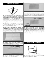
Wing Assembly ...........................................................................6
Rudder Assembly ..................................................................6
Wing Installation .........................................................................7
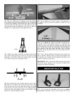
Install The Stabilizer ...................................................................7
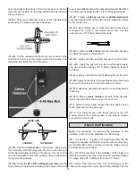
Engine Installation......................................................................8
Cowling Installation..................................................................10
Fuel Tank Installation ...............................................................10
Main Landing Gear Installation ...............................................11
Radio Installation......................................................................12
Attach the Ailerons...............................................................12
Install the Aileron Servos.....................................................13
Attach the Elevators ............................................................14
Install the Elevator Servos...................................................15
Attach the Rudder................................................................16
Install the Rudder Servo......................................................16
Tail Gear Installation ............................................................17
Throttle Servo Installation....................................................18
Receiver & Battery Installation ............................................19
Final Assembly..........................................................................19
Control Throw Adjustment ...................................................20
Control Surface Throws.......................................................20
Balance Your Model..................................................................20
Balance Your Model Laterally..............................................21
Advanced Aerobatics ...............................................................21
Preflight .....................................................................................23
Charge the Batteries ...........................................................23
Balance the Propeller ..........................................................23
Find a Safe Place to Fly ......................................................23
Ground Check Your Model ..................................................23
Range Check Your Radio ....................................................23
Engine Safety Precautions ..................................................24
AMA Safety Code (excerpt)......................................................24
General................................................................................24
Radio Control.......................................................................24
Flying .........................................................................................24
Takeoff .................................................................................24
Flying ...................................................................................25
Landing................................................................................25
Appendix: Flight Trimming ......................................................26
Flight Log ..................................................................Back Cover
Engine Mount Template ...........................................Back Cover
Your Giles G-202 ARF is not a toy, but rather a
sophisticated, working model that functions very much like a
full-size airplane. Because of its realistic performance, the
Giles G-202 ARF, if not assembled and operated correctly,
could possibly cause injury to yourself or spectators and
damage property.
To make your R/C modeling experience totally enjoyable,
we recommend that you get experienced, knowledgeable
help from an instructor with assembly and during your first
flights. You’ll learn faster and avoid risking your model
before you’re truly ready to solo. Your local hobby shop has
information about flying clubs in your area whose
membership includes qualified instructors.
You can also contact the national Academy of Model
Aeronautics (AMA), which has more than 2,500 chartered
clubs across the country. Through any one of them,
instructor training programs and insured newcomer training
are available. Contact the AMA at the address or toll-free
phone number below:
Academy of Model Aeronautics
5151 East Memorial Drive
Muncie, IN 47302-9252
Tele. (800) 435-9262
Fax (765) 741-0057
Or via the internet at: http://www.modelaircraft.org
Congratulations and thank you for purchasing the Great
Planes Giles G-202 ARF. We’d like to provide you with a bit
of history on our selection of this aircraft as the newest
release in the Great Planes scale aerobatic ARF line.
Richard Giles noted a trend in the International Aerobatic
Club (I.A.C.) competition arena toward bigger, heavier, more
costly “super monoplanes,” and he wanted to do better. The
resulting “full-scale” Giles G-200 and G-202 were designed
specifically to be a reasonably priced, low wing loading,
unlimited level, superior performer on a reasonably priced
4-cylinder engine.
Flying the Giles G-202 is a thrilling experience–as it should
be for such an aerobatic model! It doesn’t take much
elevator or aileron throw to put the Giles through its paces.
When you have a feel for your Giles G-202, the throws can
be increased to high rates (illustrated in the instructions) to
really showcase the aerobatic potential.
We hope you enjoy building and flying your Great Planes
Giles G-202 ARF as much as we did testing the prototypes.
1. You must assemble the model according to the
instructions. Do not alter or modify the model, as doing so
may result in an unsafe or unflyable model.
2. Take time to align the components straight, true and strong.
PRECAUTIONS
INTRODUCTION
PROTECT YOUR MODEL,YOURSELF &
OTHERS...FOLLOW THIS IMPORTANT
SAFETY PRECAUTION
TABLE OF CONTENTS
2


