


❏
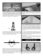
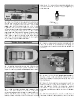
3. Test fit the stopper into the
fuel tank.
The seam
around the tank should be vertical. By holding the tank up to
the light you will be able to see where the vent tube is, in
relation to the top of the tank. If necessary, bend the vent
tube to position it about 1/8" [3mm] below the top of the tank.
When satisfied with the fit, make sure the stopper is fully
seated in the fuel tank. Tighten the stopper screw until the
plastic cap is indented about 1/16" [1.5mm]. Doing so will
lock the stopper into position. Check the clunk and pickup
tube to make sure they move freely in the tank without
binding or stopping.
❏
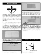
4. Cut a piece of 1/4" [6mm] thick foam rubber to 5-1/2"
x 2" [14mm x 50mm]. Place the foam onto the tank floor
inside the fuselage. Before installing the tank, make sure the
bent vent tube points toward the top of the fuselage. Apply
a bead of 100% silicone sealer around the sides of the
rubber stopper and the front edge of the fuel tank. Insert the
tank fully into the tank compartment while working the
stopper into the hole in the firewall. The silicone will seal the
opening and help hold the tank in position after it has cured.
Use two or three #64 rubber bands at the aft end of the tank
to secure it to the tank floor.
❏
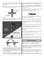
1. Locate the two
aluminum main gear
and secure them
to the fuselage using six
#6 washers
and six
6-32 x 5/8"
socket head cap screws.
Use thread locking compound on
the screws to prevent them from loosening during flight.
❏ ❏
2. Press the
landing gear cover
onto the bolts to transfer
their locations onto the cover. Remove the cover, and
remove the material from the locations to allow the cover to
set flush with the fuselage. A 1/4" [6mm] drill bit works well
for this step.
❏ ❏
3. Glue the landing gear cover into position using
medium CA or 6-minute epoxy. (You did use thread locking
compound on those six bolts?)
❏ ❏
4. Position the
wheel pant
onto the landing gear. The
bottom of the gear will be flush with the pant locks as shown
in the photo. Use a felt-tip marker to transfer the locations of
the holes in the landing gear onto the wheel pants.
❏ ❏
5. Drill the locations marked onto the wheel pants.
Use a 1/8" [3mm] drill bit for the two smaller holes. The
larger hole is drilled using a 1/2" [13mm] drill bit.
MAIN LANDING GEAR INSTALLATION
11


