


❏
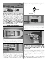
7. Cut two holes in the belly pan to access the bolts.
Measure and place a mark 4-3/4" [123mm] forward of the aft
edge on the belly pan. Place two marks 1-7/8" [47mm] from
the centerline. Drill two 1/2" [13mm] holes at the crossing of
these two lines to access the wing bolts.
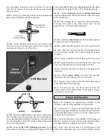
By moving the position of the clevis at the control horn
toward the outermost hole, you will decrease the amount of
throw of the control surface. Moving it toward the control
surface will increase the amount of throw. If these
adjustments don’t accomplish the job, you may need to work
with a combination of adjustments by also repositioning the
pushrod at the servo end. Moving the pushrod towards the
center of the servo horn will decrease the control surface
throw – outward will increase it.
Note:
Throws are measured at the widest part of the
elevators, rudder and ailerons. We recommend the following
control surface throws as a starting point:
Elevator
5/16" [8mm] Up
7/16" [11mm] Down
Rudder
2" [50mm] Right
2" [50mm] Left
Ailerons
3/8" [9.5mm] Up
3/8" [9.5mm] Down
These control throws are recommended for normal flying. If
you are planning on performing extreme “3D” aerobatics,
see the section on “Advanced Aerobatics” for the
recommended control throws, notes on using computer
radios and details on performing some maneuvers
associated with this exciting new form of aerobatics.
One leading cause of crashes is flying an airplane with its
control throws set differently from those recommended in
the instructions. The Great Planes AccuThrow
™
lets you
quickly and easily measure actual throws first, so you can
make necessary corrections before you fly. Large, no-slip
rubber feet provide a firm grip on covered surfaces without
denting or marring the finish. Spring tension holds
AccuThrow’s plastic ruler steady by each control surface.
Curved to match control motions, the ruler provides exact
readings in both standard or metric measurements.
GPMR2405.
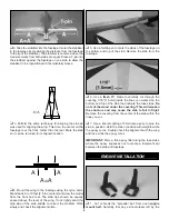
Make sure the control surfaces move in the proper direction
as illustrated in the following sketch:
Note:
This section is
VERY
important and must
NOT
be
omitted! A model that is not properly balanced will be
unstable and possibly unflyable.
❏
1. The balance point (C.G.) is located 9-1/4" [236mm]
forward from the trailing edge of the wing. Balance your
Giles using a Great Planes C.G. Machine
™
Airplane
Balancer (GPMR2400) for the most accurate results. This is
the balance point at which your model should balance for
your first flights. After initial trim flights and when you
become more acquainted with your Giles, you may wish to
experiment by shifting the balance up to 3/8" [9.5mm]
forward or backward to change its flying characteristics.
Moving the balance forward may improve the smoothness
and stability, but the model may then require more speed for
takeoff and may become more difficult to slow for landing.
Moving the balance aft makes the model more agile with a
lighter, snappier “feel” and often improves knife-edge
BALANCE YOUR MODEL
4-CHANNEL
TRANSMITTER
4-CHANNEL
TRANSMITTER
4-CHANNEL
TRANSMITTER
4-CHANNEL RADIO SET-UP
(STANDARD MODE 2)
TRANSMITTER
4-CHANNEL
ELEVATOR MOVES UP
RIGHT AILERON MOVES UP
LEFT AILERON MOVES DOWN
RUDDER MOVES RIGHT
CARBURETOR WIDE OPEN
Control Surface Throws
Control Throw Adjustment
20


