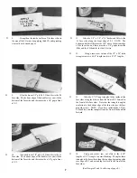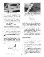
D 5. Start pilot holes with a pin at the marked locations,
then drill the holes with a 3/32" drill.
MOUNT THE STABILIZER
D 6. Trial m o u n t t h e r u d d e r h o r n s w i t h t w o 2 - 5 6 x 5 / 8 "
screws and hex nuts.
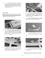
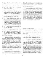
D 1. Accurately measure and mark the exact center of
the fuselage top at F-4. Also measure the width of the
stabilizer and mark the exact center at the trailing edge.
D 2. Place the fuselage on a flat surface, and hold it
down firmly with a book or other heavy object.
3. Position the stab on the stab saddle, centered side-
to-side, and pin it in place.
D
D
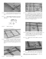
7. In a similar manner, temporarily mount the eleva-
tor control horn on the elevator. NOTE: When marking
the locations for drilling, you must hold the nylon horn
on the BOTTOM of the elevator! Use the 2-56 x 3/8"
screws and nylon nutplate to mount the elevator horn. IM-
PORTANT; Make sure the nutplate and screws of the
elevator horn do not touch the rudder when the elevator is
deflected up 1/2" Sand the bottom of the rudder if necessary
to eliminate this possibility.
D
4. While holding the stab firmly in place onto the
saddle, measure down to the flat work surface from both
ends of the slab. If one side is higher than the other, sand the
high side of the stab saddle with your T-bar sander and 100
grit sandpaper (Sand only a little at a time!). Replace the
stab in the saddle and re-check the measurements. Continue
this process until the stab is level within 1/16".
D
18
5. Again, pin the stab to the stab saddle, and measure
from the rear corners of the stab to the center mark at F-4.
Adjust the position of the stab until these measurements are
equal.
Содержание Electro Streak
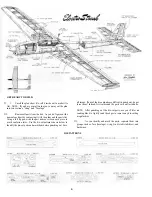
Страница 37: ...37 Use this three view drawing for planning your trim scheme...
Страница 38: ...NOTES 38...


