D
D
D
D
D
D
D
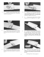
5. Begin by carefully cutting a very shallow silt in
the fin trailing edge at the hinge location. This first cut is to
establish your cut in the right place, so concentrate on
staying on the centerline and don't cut too deep!
6. Make three or four more cuts in the same line,
going slightly deeper each time. As you make these
additional cuts. work on going straight into the wood.
7. After you have cut about halfway into the wood,
you can push the blade all the way through, while "wig-
gling" the knife handle back and forth. Continue to pivot the
knife while moving the blade to both ends of the hinge
location.
8. Trial fit the hinge into the slot. If the hinge is
difficult to push in, re-insert the knife and move it back and
forth in the slot a few times to enlarge the slot.
9. Repeat the above process to cut slots at all the
hinge locations in the fin, rudder, stabilizer and elevators.
10. Assemble the rudder to the fin and the elevators to
the stabilizer (DO NOT GLUE), and check the operation of
the hinges.
TEMPORARILY MOUNT CONTROL HORNS
2 - 5 6 x 5 / 8 " S C R E W
D
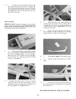
D 3. Cut and sand the two nylon rudder control horns to
the shape as shown in the "Rudder Detail" drawing on the
plan.
D
1. You'll need three nylon control horns, two 2-56
x 3/8" screws, two 2-56 x 5/8" screws, two 2-56 hex nuts, a
3/32" drill, a small screwdriver and a pliers.
2. While holding two nylon horns together at their
bases, drill 3/32" holes through the holes in one horn,
making two new holes in the other horn. The purpose of this
is to enable the horns to be bolted together on both sides of
the rudder.
4. Lay the rudder on the fuselage plan side view and
determine where the nylon control horn should be located.
Holding the nylon horn with only two holes on the left side
of the rudder, use a pencil to mark through both holes in the
horn.
2-56 x 3/8" SCREW
NYLON HORN AND NUT PLATE
17
Содержание Electro Streak
Страница 37: ...37 Use this three view drawing for planning your trim scheme...
Страница 38: ...NOTES 38...


