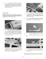
Note: Photo shows uncovered structure.
D 7. Install the rudder cables. Pass the cables through
the crimp fittings as shown on the plan, and squeeze the fit-
tings securely with a pliers. NOTE: When attempting to
run the cables from the rudder horns to the servos, it will help
to glue the end of the cable to a long piece of small diameter
music wire, then pull the cable through with the wire. Install
the EZ Connectors onto the rudder servo arms, and pass the
rudder cables through the EZ Connectors. Pull the cables
snug*, and secure them inside the EZ Connectors with 4-40
set screws, tightened down onto the cables. Pull on the
cables to check for slippage.
4-40 ALLEN
SETSCREW
•It is not necessary (or desireable) to pull the cables ex-
tremely tight, as this will cause excess friction and servo
wear. Just make sure all the slack has been taken up. Verify
this by grasping the rudder and moving it from side-to-side.
There must be no free-play in the rudder.
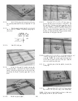
D 8. Apply 1/16" x 1/4" foam wing seating tape on
both sides of the wing saddle area to protect the wing.
D 9. Run the receiver antenna along the bottom inside
of the fuselage, and let the excess antenna length trail be-
hind.
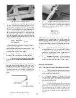
D 10. Install the 6-32 x 1/4" set screw in the aluminum
prop hub, then attach the prop hub to the motor shaft.
Tighten the set screw firmly down onto the "flat" on the
motor shaft using the hex key supplied. NOTE: When
installing the prop hub, it may be helpful to file the hex key
shorter, making it easier to use without touching the nose
block.
FILE OFF
THIS PORTION
6-32 SET SCREW
D 11. Slide the propeller onto the prop hub, and secure
it with the aluminum spinner nut and the 6-32 socket head
cap screw. Tighten the cap screw with the hex key supplied,
but do not overtighten! ("Finger-Tight" not "Wrench-
Tight" is a good rule of thumb).
6-32 SOCKET HEAD
CAP SCREW
NOTE: Although not included in this kit, you may use a 1-1/4"
plastic spinner for a sleeker appearance. If you use a spinner, you
may have to use a different length 6-32 socket head cap screw,
because of the thickness of the spinner backplate. CAUTION: If
you use a Goldberg Snap-On spinner, you must modify the snap lugs
so they insert more easily without damaging the motor.
D 12. (Optional) Install the main landing gear, using
the nylon straps and #2 x 3/8" screws provided. Drill the
wheel hubs if necessary to fit the main gear. Secure the
wheels with 1/8 "wheel collars. NOTE: A small drop of oil
on each axle will help the wheels turn freely.
D 13. (Optional) Roughen the 1/16" wire tail skid with
sandpaper, and clean it with alcohol. Glue the tail skid into
the hole you previously drilled, using CA glue or epoxy.
BALANCE YOUR MODEL
NOTE: This section If very important and must not be omitted!
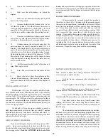
D 1. With the wing attached to the fuselage, all parts of
the model installed. Including the 7-cell motor battery,
gently turn the model upside down.
D 2. Carefully measure 3.3/4" Inches (3.75") back
from the LE of the wing along both sides of the fuselage and
mark the location of the recommended balance point. Now
turn the model right side up.
D 3. Lift the model with your index fingers at the marks
you made at the recommended balance point (or for more
precision you may lift with the eraser end of two pencils).
If the tail drops when you lift, the model is "tail heavy" and
you must add weight to the nose to balance. If the nose drops.
it is "nose heavy" and you must add weight to the tail to
balance.
(See photo at the top of the next column.)
31
Содержание Electro Streak
Страница 37: ...37 Use this three view drawing for planning your trim scheme...
Страница 38: ...NOTES 38...


