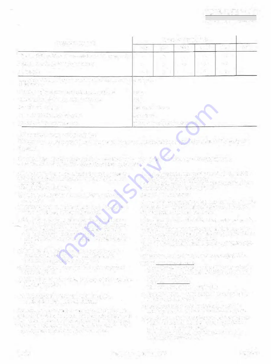
MAINTENANCE TASK
C'reaning of oiî pump ïïlter and/or renewaJ of main oil filter (see par
.
6.9
Cleaning of suction gas strainer (see par. 6.11)
Oil change 2)
lnspeçlion and, if required, replacement of filter element in secondary
oil separator 3)
Checking coupling alignmentand tightening of ooupfing bolts
Tightening of motor and compressor mounting bolts
lnspection rotor end play
lnspection capacity control valve guide
General overtiaul of compressor unit
} Dependin_g on degree of contamination
GRBSSï:i
BEOIENIIIGSV00A5CHAIFT�
�--I.EL0'1NS'TR)CTl0N
HOURS OF OPERATION 1)
0-50
200
2500
5000
7500
ETC.
X
X
X
X
)(
-
X
X
X
)(
-
X
-
-
-
alter 3 years
yeany
year1y
yearfy
or
5,000
ho11rs
20,000hours
alter six years or 40,000 operating hours
2)
Every three months or 2,000 t,ours unless uslng oil analysis. Maximum time six months. Refer to Par. 6.6 uoit analysis"
3) lt
f
i
tted
For most of the maintenance tasks, first evacuate the compressor package in order to remove the retrigerant gas.
After completion of maintenance, purge the compressor package.
Oil can also be
.
charged by reducing the suction pressure
below atmospheric pressure and if no hand or electric oil
pump avaifable.
The procedure is as follows:
a) Connect a hose to the oil charging vaJve on the suc
tion side.
b) Fill the hose with oil and emerge its free end in a reser
voir containing a sufficient amount of all.
c) Close the suciion stop valve to such an e_xtent that the
suction pressure falls below the atmospheric pressure.
lf necessary, shunt the electric contacts of the mini
mum suction pressure safety switch (do not forget to
remove this shunting after completion of maintenance
work).
d) Keep the oil charging valve open Uli the oil ln the oil
separator has reached the required level again.
Take care that no air is being drawn in.
e) Slowly open the suction stop valve in order to prevent
liquid carry-over.
f) Remove the hose and replace the cap nut with gasket on
the charging valve.
6.9 MAINTENANCE OF MAIN OIL FILTER, OIL
STRAINER AND OIL PUMP FILTER
SinOQ ther<.> �re two differont oil :.y:.tcm:;
1
tho GSL.P P.i.ok
ages can be distinguished in two designs; with a full-flow oif
pump for systems with a low oil pressure difference of max.
-◄ .
5 bar and with a lubrication oil pump (for systems with a
,,sh oil pressure difterence of 1.5 bar and over.
In general, the maintenance tasks described hereafter can
be used for both package designs.
For flow diagrams needed for ti-acing of the pan identîfica
tion nurnbers, reter to pages
3.3
to
3.6.
MAIN
FLOW OIL FILTER
A warning signal activated by the pressure drop sensing de
vice, indicates when the main flow oil filter element (20),
due to pollution, requires replacement.
In the case of a single oil filter, the compressor package has
to
be
stopped.
In the case of a double oil filter, the spare filter stop valve
must be opened and the stop valves of the polluted oil filter
closed without stopping the compressor.
To re place the maîn flow oil filter elements proceeds as fel
lows:
a) Carry out the shUt down procedure in paragraph 7.3.
b) With lubrication-oil pump:
Close the filter isolating stop valves (13), oil pump suc
tion stop valve (13) and stop
valve
(13) in the balanoe
piston oil suppfy line.
With
tuU-flow-ojl pump:
Close the filter outlet stop valves (13)
c) Open the oil drain valve (12) at the bottom of the filter
housîng and drain the oil.
d) Rernove the fitter cover and withdraw the filter ele
rnw-J1t �ftc;:r rcm9vin3 th� loek nut :and mtaining plate
e) As the oîl ftows through the filter element trom the out
side inwards, the accumulated sediment should be
removed from the filter housing.
Take care that no dirt enters the outtet line during
cleaning of the filter housing.
92.01
Compressor Package GSLP
Page6.3


