maximum. lf it does not read in this maximum posi
tion, loosen the cam set screw and turn the indicator
pointer to the correct number of revolutions as given
ln table 4.3 on page 4.8.
1) Check to see the indicator pointer read the maximum
number of revolutions as given in table 4.3 on page 4.8.
Correct the posîtion of the indicator pointer if necessary
by toosening the set screw with a 3/32 Allen wrench and,
after resetting the pointer, tighten the set screw Very tight
ly to prevent loosening.
m)
Move
the capacity control slide Valve to thè minimum
tor fully unloaded position by turn1ng the output shafl
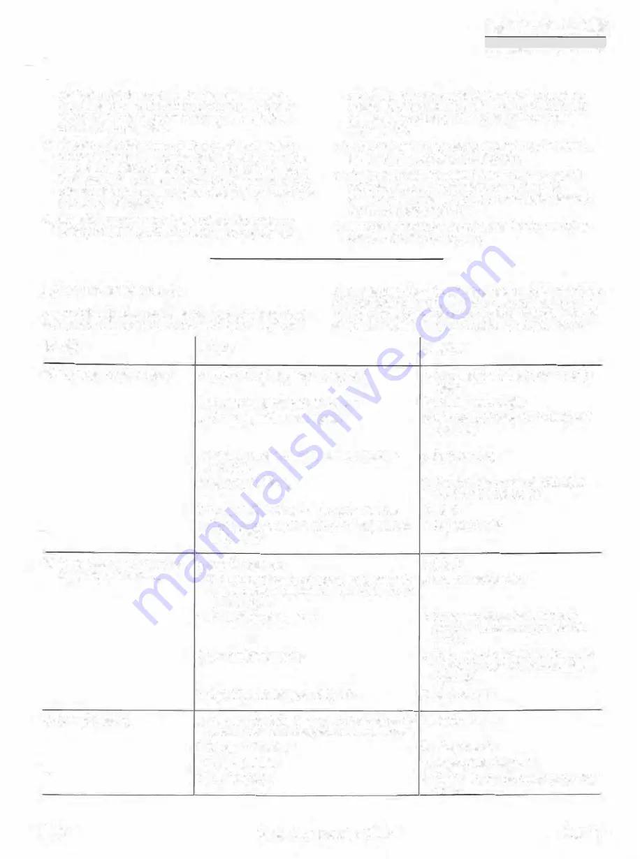
6.13 FAULT-FINDING TABLE
, ne faulMinding table below may be helpful to 91..11ckly trace
and remedy failures that interfere
with
the proper operation
FAULT
CAUSE
GRBSSa
IIEDll;faNCSV00RSOIAlfTl!IEl>IEBS,fJ(Uêl!IJi;G
INSTIIUCTIDH iWUWAWll.liL mNSmlJCTID>i
counterclockwise the number of revolutions as given
in table 4.3. The indicator pointer should read zero. lf
necessary, reset thîs pointer to zero with an 3/32
Allen wrench.
n) Correct the minimum position cam as given in steps k,
1 and m tor the maximum position cam.
o) Put actuator In brak.e positîon. Reconnect the control
cabinet to the electric supply line and check the
above adjustments with power to the electric val\te ac
tuator as in paragraph 4.15.
p) Mount the actuator cover and install the four mounting
screws. Start the compressor.
of the packa_ge. lt is emphatically pointed out that the cause
of a fai1ure must aften be sought in the refrigeration installa
tion itself. Therefore, it is necessary in addltïon to this fault
finding table, also to consult the plant operation manual.
REMEDY
A) Compressor will not start
1 . One of the safety switches tripped
1. Remove cause. Check setting and
reset
2. No power supply to con trol circuit
2. Check power supply
3. Minimum position cam slipped
3. Aeadjust per para. 6.12 aJ'ld tighten
set screw
4. Minimum position micro switch on actuator
4. Purge system
detective
5. Oil pump detective
5. Check that the motor is running in
correct direction. Repair
6. Plugged oil strainer in oil pump suction line
6. Clean
7. Start.up oil pressure switch out of adjustment
7. Adjust or repair
or detective
B) Compressor shuts down im-
1
.
Low oil pressure
1. See C
mediately a
f
ter startin.9
2. The return valve after oil pump leak.s excessi-
2. Replace return valve
vely, allowing oil to drain from filter when com-
pressor stops
3. High discharge pressure
3. Check condenser fan and water
pump and if necessary purge con-
denser
4. Low suction pressure
4. Open suction valves. Check capaci-
ty control to see îf it unloads auto•
matically
5. High oil or discharge temperature
5. See F and G
C} Low oii pressure
1. OH pressure relief valve and/or oil pressure
re-
1 . Adîust or repair
gul:::iting valvA out of adju5:tmAnt or defec!ive
2. Plugged oil strainer
2. Clean straîner
3. Plugged oil filter
3. Replace filter element
4. Low oll charge
4. Check oil level with compressor shut
down
92.01
Compressor Package GSLP
Page6.5


