- Have available the following (measuring) tools;
- clean feeler gauges trom 0.025 mm to 0.5 mm
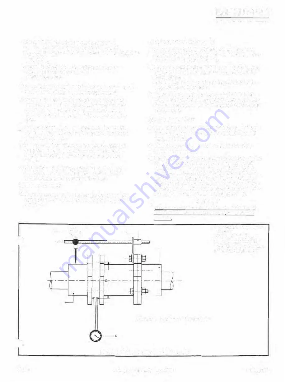
- two dlal indicators with attachments and indicator jig (see
fig. 4.2)
- a straight edge
- a crow bar or streng lever to lift the drive motor
- shims with various thicknesses
- (metric) spanners
8) MOTOR
AXIS
ALIGNMENT (only if electric motor have
been recovered after servicing or replacement)
1} Ternporarily place the elëctrîc motor onto the base
frame and move the motor to the compressor shaft
end until the distance between both shaft ends is
about 100 or 140 mm, depending on used coupling
size.
2) Using a straight edge, roughly align motor axis with
the compressor axis and finally check and/or correct
the shafts interspace.
3) Note the axis level drfference between the shafts of
compressor and motor. This difference shows the
total shim spacing between motor feet and base
frame.
4) To facifitate easy alignment ensure that the motor
shaft is lower than the compressor shaft (so that
height increases are possible with shims}.
5) Remove the motor.
6) Press the motor coupling flange onto the motor shaft
end until the end façes of motor shaft and coupling
are flush.
1--0
2--
s
C}
PRELIMINAAY ALJGNMENT
GRHSSa
IIE!lEMNG$!1QOIISOIRIFTIIIEmlEIIS,ANI.EITIINO
11,smuc:tioN l&AIIIWAIAHI.EL o,�
7) Definitely place the motor onto the base frame and
securely align the coupling so as described hereaf!er
in the final alignment procedure.
8) Mount the steel plate packs with spacer inbetween in
such a way that the bolt holes are aligned opposite
the recesses.
Assembling rule:
Always
fit the rfng packs (4 in fig.
4.1) onto the flanged parts.
9) Tlghten up all coupling fasteners as glven in Table
(4.1 ), install the coupling guard only after motor rota
tion check and proceed with Paragraph 4.9 KPackage
pressure test.
D) FINAL ALIGNMENT
a) Refer to figure 4.2 mount the cleaned spacer without
the plate packs onto the motor coupling flange and
tightened bolts.
b) Clean the plane flange surface and the hub of the
compressor coupling.
c) Agaîn refering to figure 4.2 attach the concentricity dial
indicator secure1y to the compressor coupling hub
using a dia! indicator jig. Move the dia! indicator to
zero degrees (top position of hub) and set indicator to
zero. Check attachment of the indicator by rotating
the shatts of compressor and motor tögether 360 de
g rees or one revolution. lf the dia! reading should not
return to zero check the indicator jig mountlrig.
d)
IMPORTANT
The
maximum allowable coupling concentricity and
aauutadty misalignmeat is
o os
mm
(total indicator
reading/
3
1. concent11ctty m,salignment dral
indicator
2. lndIca10r mounung Jlg
3. electr1c motor c:oupüng flange
4. angularity misaJignmentdlal
,nri,cator (în erevation and planj
5. compressor coupl,ng fl.inge
D � indicator plungerdrc1e diameter
FIG. 4.2 ALIGNMENT ARRANGEMENT
92.01
Compressor Package GSLP
Page 4.3


