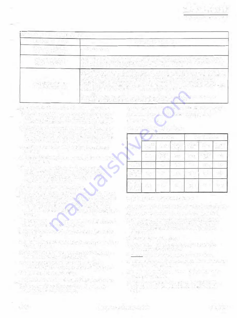
T ABLE 7..3 ROTOR END PLAY TOLERANCES
MEASUREO END PLAY
(0.0005
to
0.0010 inch)
0,0127 to 0.02-54 mm
Bearings are sound.
CONDITlON AND ACTION
GRB&Sa
8EDENINQSVOORSCHRIFT,11ETREBSAHL.EfflJNC
IN$Tl>llCTIOOI IWltW.MANIIELO'IIISTRUCT101<
(0,010 to 0.0020 inch)
Beaöngs are questionable. Remove the coupllng, pip1ng, shaft seal and outJet cover as in section 7, 11.
Inspeel the out board bearing raceway and rolling elements for visible damage (eg pil marks, scoring or
0.0254 to 0.0508 mm
loose cagesJ. Re•inspect
every
1,000 hours
if
no sign of pitting
or
scoring,
Remove the coupling, piping,
shaft
seaJ and outlet cover as fn paragraph 7.11, Inspeel Ine
outboa-rd
bearing raceway and rolling elements for vlslble damage (eg pit marks, scoring or lease cages). Push the
rotor by hanc;I (501b or 200 Non the lever) to the discharge end of the compressor. Measure the
(0.0020 inch and above}
clearance between the end face of the rotor and the discharge housing by inserting feelèr gäuges
0.0508
mm and above
through thè discharge port with the capacity controf sfîde valve in the maximum position. This clearance
shoi,Jld be (0.002 inch to 0.005 inch) 0.0508 mm to 0.127 mm for all models.
Contact Grasso with the measurements
of
both the end play and the rotor wfral clearance and the
Ci!:!Dif;m:S'isu :ie[iill num�t as the thrust bearings may have to be replaoed.
a) Carry out the shutdown procedure in paragrap.h 7_.3_
,) Referring
to
fig.
7.5.
remove the male rotor inlet bear
ing cover including 0-ring by removing the bolts. Use
screwdriver to part the cover from the inlet housing.
c) lnstall an eye bolt from table 7.4 in one of the tapped
holes whic� is exposed on the end of the balance pis
ton. Screw rn an eye bolt from table 7.4 in place of
the
screw taken out of the male rotor inlet bearing cover.
d) lnstall a second eye bolt from table 7.4 into the inlet
housing.
e) lnstaH a (three inch) 76.2 mm contact point extension on
a dial indicator.
f)
Mount a magnetic dial indicator on the compressor
casting with the contact point of the dial indicator
touching the male or female rotor, depending on
which rotor is being checked.
g) Set the dïal indicator reading to zero.
h) With a (3/4 inch) 19 mm diameter by (one
toot)
305 mm
1
long bar placed through both eye bolts and by using the
,
eye bolt in the inlet housing as a fulcrum, a,pply hand
force [approx.
(50
Ibs)
220 NJ
using a back and forth
movement to create end play {see figure 7.5 for a typical
set up).
1) Read the end play movement on the dia! indicator when
the hand force is applied to the bar.
j) Compare the rotor end play with the tolerances in table
7.3 above.
k) After one rotor is checked, follow the same procedure for
the second rotor_
1) Reassemble parts with
new
gaskets and 0-rings (eg
cover and (fe)male rotor infet bearing).
m) Tighten the ferry head screws to the torques tor
Grade 8 condition B fasteners in table 7 .1 in para. 7.4.
n) Close tne pressure satety valve.
o) Open the suction stop valve and discharge stop valve.
,,
lf the compressor is fitted with an economizer port,
open the economizer stop valve.
q) Reconnect the control cabinet to the electric supply line.
r) Reconnect the starter to the electric supply line.
s) Start the compressor
.
T ABLE 7.4 EYE BOLT DETAILS
Rotor eye bolt
Housing eye bolt
Thread
Pitch
Shank
Thread
Pitch
Shank
Model
dia.
length
dia.
length
inch
thread/
inch
inch
thread/
inch
inch
inch
GSL65
5/16
18
3.5
1/2
13
1.5
GSL85
3/8
16
4.0
1/2
13
1.5
GSL125
GSL165
GSL180
3/S
16
5.0
5/8
11
1.75
GSL240
7.10 THRUST BEARING INSPECTION
A) REMOVAL OF OUTLET END COVER (refer to figure 7_6)
a) Carry out the shut down procedure in paragraph 7
.3.
b) Place the capacity control slide valve in the maximum
position by rotating the output shaft clockwise (ma
nually
or
with
a suitable wrench after pulling out the
black knob).
c} Remove the coupling guard.
d) Remove the coupling spacer (incl. plate packs), the
rotor coupling flange and key.
e)
Do not
move either the compressor or the motor.
f)
Remove the high discharge temperature thermostat bulb
from the discharge pipe.
g} nemove the di�ch0r9e pipe betweçn the;
oomprc;,;,or
and the oil separator.
h} Remove the discharge pressure stop valve trom the
outlet cover and disconnect the shaft seal oil supply
line.
92.01
Compressor Package GSLP
Page
7.7


