


2 of 20
Cleaning ...........................................................Pg 13
DIP Switch Settings ........................................Pg 13
Quick Setup .....................................................Pg 14
Control Settings ..............................................Pg 15
View Menu
..............................................Pg 15
Adjust Menu
...........................................Pg 16
Application ......................................................Pg 17
Error
Messages
......................................Pg 19
Technical Data ................................................Pg 20
How To Use The Data Brochure
User Interface
The GEO 360 uses a Liquid Crystal Display (LCD) as the method of supplying information. You use the LCD in order to set up and
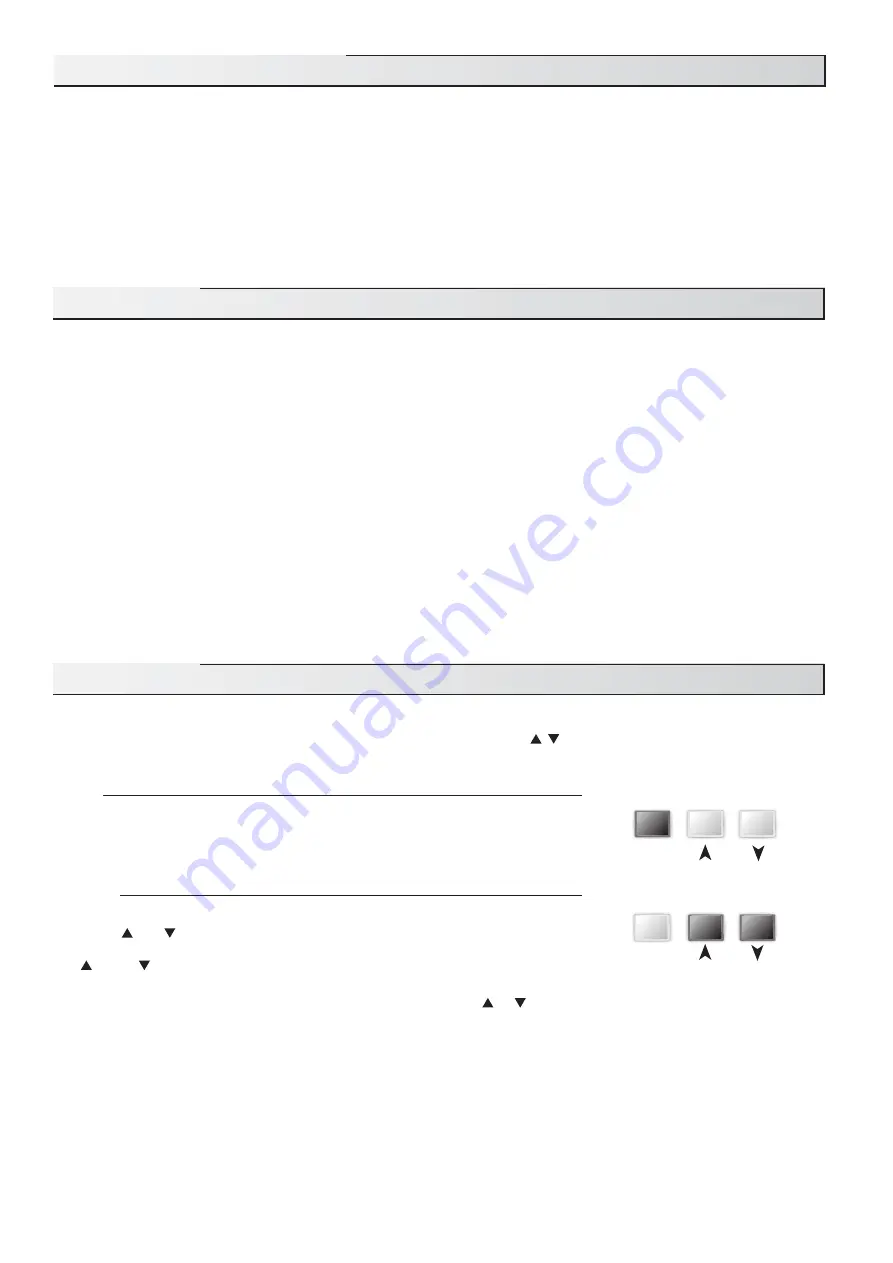
monitor the operation of your system. The GEO 360 has three push buttons (
Item
, , ) for selecting, viewing, and adjusting settings.
As you program your control, record your settings in the ADJUST menu table which is found in the second half of this brochure.
Item
The abbreviated name of the selected item will be displayed in the item field of the
display. To view the next available item, press and release the
Item
button. Once
you have reached the last available item, pressing and releasing the
Item
button will
return the display to the first item.
Adjust
To make an adjustment to a setting in the control, press and hold all three buttons
(
Item
, and ) for 1 second. The display will then show the word ADJUST in the
top right corner. Then select the desired item using the
Item
button. Finally use the
and/or button to make the adjustment.
To exit the ADJUST menu, either select the ESC item and press the
or
button, or leave the adjustment buttons alone for 20
seconds.
When the Item button is pressed and held in the VIEW menu, the display scrolls through all the adjust items in both access
levels.
Additional information can be gained by observing the status field and pointers of the LCD. The status field will indicate
which of the control’s outputs are currently active. Most symbols in the status field are only visible when the VIEW menu is
selected.
User Interface ..................................................Pg 2
Description of Display Elements ..................Pg 3
Sequence of Operation ..................................Pg 4
Section A:
General Operation ..............Pg 4
Section B:
Mixing ..................................Pg 5
Section C:
Boiler Operation .................Pg 8
Installation .......................................................Pg 9
Electrical
Connections
..........................Pg 10
Testing The Wiring .................................Pg 12
This brochure is organised into four main sections. They are: 1)
Sequence of Operation,
2)
Installation,
3)
Control Settings,
and 4)
Troubleshooting.
The Sequence of Operation
section has three sub-sections. We recommend reading Section A:
General Operation
of the Sequence of Operation
, as this contains important information on the overall operation of the control. Then read the sub-
sections that apply to your installation. For quick installation and setup of the control, refer to the
Installation
section,
DIP Switch
Settings
section, followed by the
Quick Setup
section.
The
Control Settings
section (starting at
DIP Switch Settings
) of this brochure describes the various items that are adjusted and
displayed by the control. The control functions of each adjustable item are described in the
Sequence of Operation
.
Table of Contents
Item
Item


