37
36
Grange Machinery Ltd.
Sproatley Grange
Hull
HU11 4PT
M: 07918 515385
T: 01482 815711
E: [email protected]
W: www.grangemachinery.co.uk
Grange Machinery Ltd.
Sproatley Grange
Hull
HU11 4PT
M: 07918 515385
T: 01482 815711
E: [email protected]
W: www.grangemachinery.co.uk
18.0 Warranty
The Grange Machinery Ltd. 3m Low Disturbance
Toolbar is covered for a period of 12 months from
the date of delivery to farm (which is recorded
on our files) against faulty components and/or
bad workmanship. All products are checked and
hydraulically tested prior to delivery/collection.
We cannot be responsible for claims arising from
ignorance, occurrences outside our control, such as
accidents, and malicious damage.
Warranty claims for damage during transport
Damage occurred during transit via an external
haulier must be reported immediately upon
unloading and signing for the item. The limit of our
liability to undertake repairs to products damaged
during transit is dependent on signing for any
damaged product upon delivery as “DAMAGED”.
Machines must return to Grange Machinery Ltd
to have any warranty work carried out. Grange
machinery Ltd genuine pars must be used to keep
warranty valid throughout use.
Any modification or tampering to the Grange 3m
LDT without prior consent from Grange Machinery
Ltd will invalidate the 12 month machine warranty.
The content of this operator manual are correct at
the time of print but may be subject to additions
or change at any time in the future. Replacement
operator manuals must be ordered in relation to the
model and serial number provided.
I
F
,min = (
I
R
x
(c+d))-(
T
F
x
b
)+(0,2
x
T
E
x
b)
a+
b
Appendix 1.0: Example calculations: Ref Fig 4.0
I
R
Please note these are indicative calculations
using industry examples for typical 200hp
tractor specifications. Due to the combination
of the Grange 3m LDT and 2nd stage cultivation/
seeding equipment the tractor machine
combination can become unstable. The following
expression can be applied for the calculation
of the minimum ballasting at the front (IF
min) which allows to have a load on the front
axle equal to 20% of the unladen mass of the
tractor. The operator of the Grange 3m LDT and
and coupled 2nd stage cultivation / seeding
equipment must input the relevant values for
the tractor and 2nd stage cultivation / seeding
equipment they are using. In addition variables
such as tractor tyre pressures also need to be
checked and set to suit operational conditions.
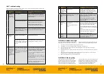
Key
Definition
Values inputted
T
E
[kg]
Mass of un-laden tractor
7300Kg
T
F
[kg]
Front axle load of un-laden tractor
2701Kg
T
R
[kg]
Rear axle load of un-laden tractor
4599Kg
I
R
[kg]
Combined mass of rear-mounted implement / rear
ballast (Grange 3m LDT)
1250kg
I
F
[kg]
Combined mass of front mounted implement /
rear ballast
See calculations below
a
[m]
Distance from centre of gravity for combined front
mounted implement / front ballast to front axle
centre.
1.48m
b
[m]
Tractor wheelbase
2.884m
c
[m]
Distance from rear axle centre to centre of lower
link balls.
1.1m
d
[m]
Distance from centre of lower link balls to centre
of gravity for combined rear-mounted implement /
rear ballast. (Grange 3m LDT)
0.57m
1.0
Example tractor specifications: Typical 200hp, including integral front linkage and
weight block with only the Grange 3m LDT attached;
IF (min) = (1250x(1.1+0.57)) – (2701x2.884) + (0.2x 7300 x 2.884) / 1.48 + 2.884
IF (min) = (1250x(1.67))-(7789)+(4210) / 4.364
IF (min) = - (minus) 342kg (e.g no front counterbalance required)
2.0
Example tractor specifications: Typical 200hp including integral front linkage and
weight block with the Grange 3m LDT attached and also a 2nd stage cultivation/
seeding equipment with a drawbar load of 2500kg. The clevis hitch on the Grange
3m LDT is located at approximately the same position as the units centre of gravity.
Therefore the
IR = ( 2500kg)
IF (min) = (3750x(1.1+0.57)) – (2701x2.884) + (0.2x 7300 x 2.884) / 1.48 + 2.884
IF (min) = (3750x (1.67))-(7789)+(4210) / 4.364
IF (min) = + 615 Kg (e.g 615kg of front counterbalance required on the tractor)


