23
22
Grange Machinery Ltd.
Sproatley Grange
Hull
HU11 4PT
M: 07918 515385
T: 01482 815711
E: [email protected]
W: www.grangemachinery.co.uk
Grange Machinery Ltd.
Sproatley Grange
Hull
HU11 4PT
M: 07918 515385
T: 01482 815711
E: [email protected]
W: www.grangemachinery.co.uk
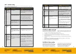
FIG 4.0 CALCULATION TO DETERMINE TRACTOR FRONT BALLAST REQUIREMENT
Key
Definition
Where to find values
T
E
[kg]
Mass of un-laden tractor
1
T
F
[kg]
Front axle load of un-laden tractor
1
T
R
[kg]
Rear axle load of un-laden tractor
1
I
R
[kg]
Combined mass of rear-mounted implement / rear
ballast
2
I
F
[kg]
Combined mass of front mounted implement /
front ballast
To be calculated
a
[m]
Distance from centre of gravity for combined front
mounted implement / front ballast to front axle
centre.
1/ FBD
b
[m]
Tractor wheelbase
1 / 3
c
[m]
Distance from rear axle centre to centre of lower
link balls.
1 / 3
d
[m]
Distance from centre of lower link balls to centre
of gravity for combined rear-mounted implement /
rear ballast.
0.57m. (Design specification of
Grange 3m LDT).
1
See instruction handbook of the tractor. Check
maximum front axle permissible load.
2
The mass of the Grange 3m LDT
without a 2nd
stage cultivation/seeding equipment coupled to the
clevis hitch or linkage arm assembly is
1250kg.
When connecting any other equipment to the 3m
LDT the drawbar / hitch mass (Kg) of the 2nd stage
cultivation/seeding equipment must be added that
of the Grange 3m LDT [1250Kg] to establish an
overall kilogram loading on the tractor hitch, value
IR.
Please note that the maximum mass of seed or
other materials held in a hopper in the 2nd stage
cultivation/seeding equipment needs to be included
in the overall value of
IR’
FBD
[m]
FBD: Front balance distance
Measurement of the centre of gravity of the tractor
front weight assembly or centre of gravity of front
mounted implement to the tractor front axle.
Refer to operator’s manual for front mounted
implements to verify the position of the centre
of gravity.
3
To be measured
FIG 5.0 CORRECT LINKAGE CONFIGURATION IN WORKING POSITION
10.0 Setting up machine for work
When setting up the tractor for connection to the Grange 3m LDT, firstly adjust the
lower link check chains to reduce the lateral sway as much as possible (ideally less
than 20mm). Ensure that the linkage balls are not corroded and can turn on the pins.
The correct top link setting is important to ensure the Grange 3m LDT is safe and
efficient in operation, ref Fig 5.0. Fig 6.0 shows a correctly configured Grange 3m LDT
coupled up to 2nd stage cultivation / seeding equipment via the link arm hitch.
The lower link arms should remain locked in position during all work and transport
mode operations. Minimal adjustment of the link arms can provide additional
clearance over obstacles. Activate the auxiliary hydraulics to raise the cutting discs
and legs to their top position to clear any surface obstacles. This setting then
provides a consistent coupling height for 2nd stage cultivation/seeding equipment
connected to the clevis hitch.


