21
20
Grange Machinery Ltd.
Sproatley Grange
Hull
HU11 4PT
M: 07918 515385
T: 01482 815711
E: [email protected]
W: www.grangemachinery.co.uk
Grange Machinery Ltd.
Sproatley Grange
Hull
HU11 4PT
M: 07918 515385
T: 01482 815711
E: [email protected]
W: www.grangemachinery.co.uk
9.0 Coupling up
Before operational use, the tractor front ballast needs to be checked to ensure
there is sufficient stability when coupled up the Grange 3m LDT and any 2nd stage
cultivation/seeding equipment. The diagram and example calculation in Fig 4.0
demonstrates the values which need to be established. Note the value
d [m] is taken
from the centre of the linkage balls to the centre of the lifting eyes (e.g. the Grange
3m LDT centre of gravity)
Please refer to the definitions in the table in section
9.0 which identifies the variables which are required
to calculate the value (kg) for the front ballast;
IF min
The value
IF min allows to have a load on the front
axle equivalent to 20% of the un-laden mass of
the tractor.
Please refer to Appendix 1.0 at the rear of the manual
for example calculations.
Fig 4.0 Calculation to determine tractor front
ballast requirement
I
F
,min = (
I
R
x
(c+d))-(
T
F
x
b
)+(0,2
x
T
E
x
b)
a+
b
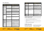
8.5 Attachment option
FIG 3.0 COMPONENT IDENTIFICATION
REAR CLEVIS HITCH WITH 2ND STAGE CULTIVATION /
SEEDING EQUIPMENT COUPLED UP
ATTACHMENT PIN FOR REAR HITCH COMPONENT
STRAPPING
POINT FOR
TRANSPORT
CLEVIS HITCH
FOR TOWED
2ND STAGE
CULTIVATION
/ SEEDING
EQUIPMENT
LYNCH
PIN FOR
SECURING
ATTACHMENT
PIN


