background image

GRANDVIEW ENGINEERING SOLUTIONS, LLC

Grandview RemoteConnect Owner’s 
Manual 

Grandview Engineering Solutions 
4831 N Warren Drive 
Columbus, IN 47203 

Publication Date: August 19, 2019 
Publication Number: 006-0819 

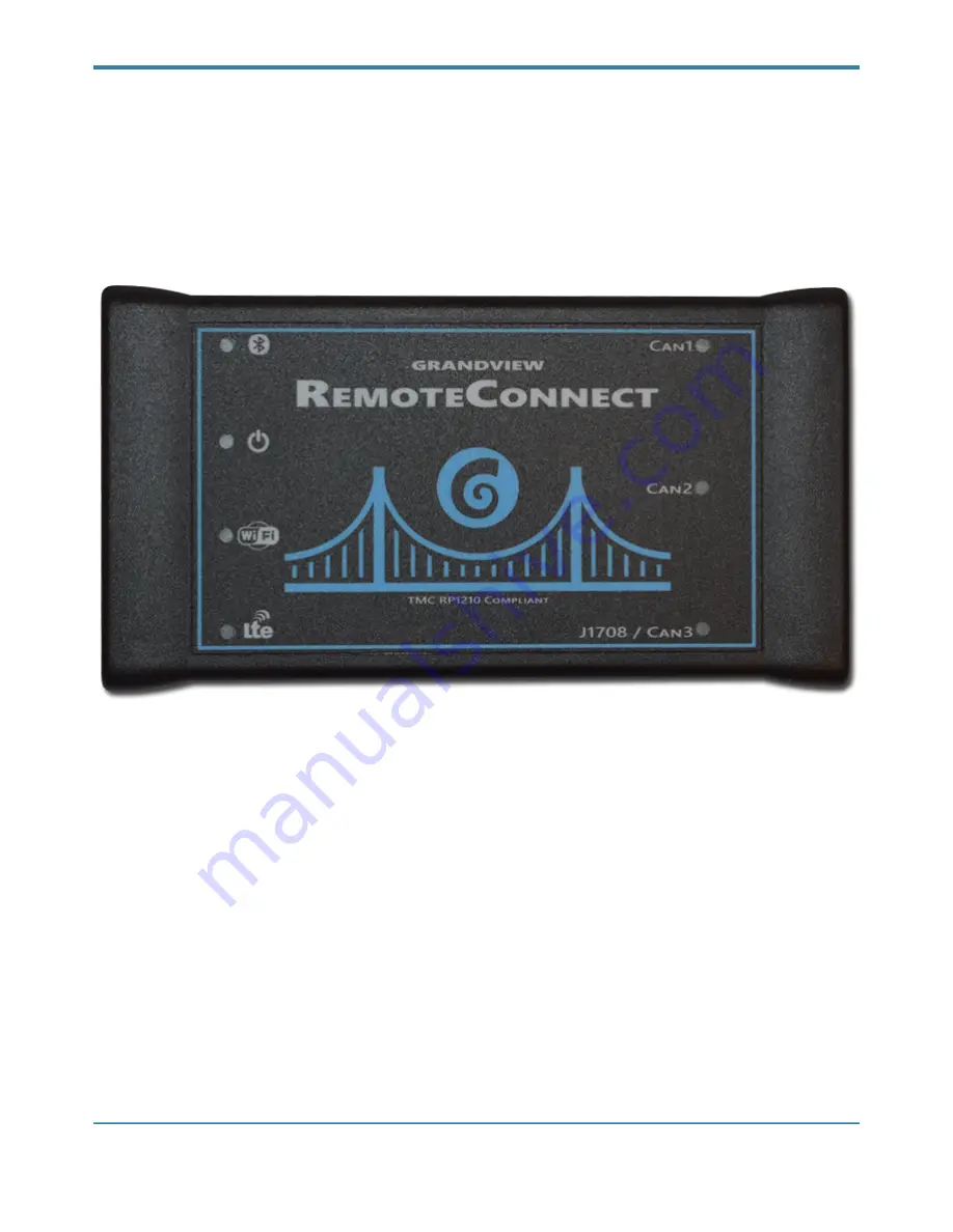
Grandview RemoteConnect

Owner’s Manual

Page 

!

 of 

!

1

26

Содержание RemoteConnect

Страница 1: ...ONS LLC Grandview RemoteConnect Owner s Manual Grandview Engineering Solutions 4831 N Warren Drive Columbus IN 47203 Publication Date August 19 2019 Publication Number 006 0819 Grandview RemoteConnect...

Страница 2: ...content of this manual is furnished for informational use only is subject to change without notice and should not be construed as a commitment by Grandview Engineering Solutions LLC Grandview Engineer...

Страница 3: ...EMENTS 7 DEVICE FEATURES 8 Installing the Drivers and Setting Up the Device 10 INSTALL THE DRIVERS 10 USING THE GRANDVIEW CONFIGURATION TOOL 14 PAIRING GRANDVIEW REMOTECONNECT WITH PC 17 CONNECT THE G...

Страница 4: ...lowing sections Table of Contents helps you to find the information you are looking for quickly and easily Using this Manual provides an overview of this manual Introducing the Grandview RemoteConnect...

Страница 5: ...the operator or to bystanders Example Keep all cables clear of moving or hot engine parts Troubleshooting Information intended to help you to address or anticipate potential issues are presented in t...

Страница 6: ...s from anywhere you have cellular coverage This section introduces the Grandview RemoteConnect and provides details regarding the interface with your PC Kit Contents page 6 Product Specifications page...

Страница 7: ...0 mm x 75 mm x 30 mm Weight 8 oz 200 g Power Requirements 5 VDC 350 mA maximum Operating Temperature 0 to 70 C API Driver TMC RP1210A RP1210B and RP1210C compliant Vehicle Protocols Supported J1708 J1...

Страница 8: ...cted to 12VDC USB is not sufficient for the radio s power needs The Grandview RemoteConnect will function according to the wireless configuration settings When the WiFi LED is off this means that the...

Страница 9: ...3 LED is multiplexed While the Grandview RemoteConnect adapter is physically connected to different data links it shares the LED between the J1708 network and the CAN 3 channel This is because the J1...

Страница 10: ...us an e mail at support grandviewengineeringsolutions com INSTALL THE DRIVERS Prior to using the Grandview RemoteConnect adapter you must install the necessary drivers and software The Grandview Remot...

Страница 11: ...ations 6 Click Next The License Agreement screen is displayed 7 Read all the information on this screen then click I accept the terms in the license agreement If you do not agree to the terms click Ca...

Страница 12: ...tallation begins and the following screen is displayed 9 Click Install If you are running Windows 7 or higher the following Windows Security dialog may be displayed 10 Click Yes to continue Grandview...

Страница 13: ...briefly while the installation continues This installation will add a USB device driver to your PC 12 Click Yes Wait again for the Installation Complete screen to be displayed 13 Click Finish Grandvie...

Страница 14: ...dge Grandview Configuration The application is started and the Configuration tool Updates screen is displayed 2 Connect a Grandview RemoteConnect data link adapter to the PC using the USB cable 3 Afte...

Страница 15: ...is information can be useful when troubleshooting connection problems If a newer version is available the Update button will be enabled 1 Click the Update button 2 Wait briefly while the Grandview Rem...

Страница 16: ...or can communicate with a wired network Name This name will be displayed in the Grandview Discovery tool The name and SSID do NOT have to match SSID The name assigned to a WiFi network In Ad hoc mode...

Страница 17: ...eone from Grandview Engineering Solutions will make contact with you to start a LogMeIn session 2 We will use Windows File Explorer to navigate to this path C ProgramData Grandview Engineering Solutio...

Страница 18: ...diagnostic connector 3 Key ON the vehicle The vehicle s diagnostic connector is typically located under the dashboard on the driver s side or beside the driver s seat It can also be located in the en...

Страница 19: ...dview Engineering RP1210 drivers installed on the PC 3 Use the Device drop down of the Adapter setting to select the appropriate device see the following sections for connecting using USB WiFi Bluetoo...

Страница 20: ...nnect Using WiFi To connect the Grandview RemoteConnect to your PC using WiFi 1 Confirm the Power and WiFi LEDs are illuminated blue on the Grandview RemoteConnect If not refer back to the Connect the...

Страница 21: ...PAN This means that the Grandview RemoteConnect will broadcast its own network After pairing with this device you will have connect your PC to this network The SSID network name will be GrandviewBT l...

Страница 22: ...Grandview Engineering Solutions the first time only to configure your PC for communications with your Grandview RemoteConnect device If not refer back to the Pairing Grandview RemoteConnect with PC s...

Страница 23: ...tal statistics If a connection error is displayed in the QuickView status window In the Settings make sure that the Vendor is GES32 and the Device is USB or WiFi Check the adapter cable connections be...

Страница 24: ...iFi BT or Cellular 2 Using an RP1210 compliant application begin whatever connection procedure is typical for that application 3 The Discovery Tool is automatically launched if a wireless device Bluet...

Страница 25: ...6 5 Detroit Diesel Diagnostic Link 8 Eaton Service Ranger Freightliner ServiceLink Hitachi Maintenance Pro Dr Navistar ServiceMaxx Noregon JPro Paccar ESA Perkins Electronic Service Tool Pocketfleet...

Страница 26: ...elease Date January 29 2019 Improved the J1939 and J1587 protocol software Added support for more OEM RP1210 applications Detroit Diesel Calibration Tool Diagnostic Link 6 5 and Freightliner Service L...

Отзывы: