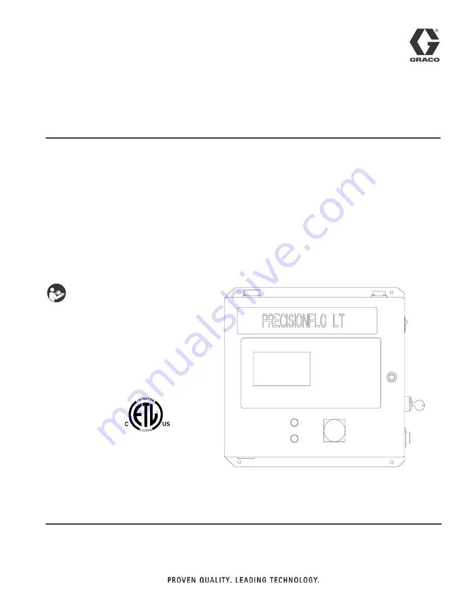
background image

Instructions

PrecisionFlo LT

Standard, Series B

Electronically controlled fluid dispensing packages. For professional use
only.

• Pneumatically operated fluid regulators

• EasyKey keypad interface

Not for use in explosive atmospheres.

See page 2 for a list of models and maximum working pressures.

See page for Table of Contents.

Important Safety Instructions

Read all warnings and instructions in this manual.
Save these instructions.

9902471

Certified to CAN/CSA C22.2 No. 1010

Conforms to

UL 3121-1

309738L

ENG

Содержание 234129

Страница 1: ...id regulators EasyKey keypad interface Not for use in explosive atmospheres See page 2 for a list of models and maximum working pressures See page 4 for Table of Contents Important Safety Instructions...

Страница 2: ...li cal flow meter 6000 psi 41 MPa 414 bar 100 4500 psi 0 7 31 MPa 7 310 bar 100 psi 0 7 MPa 7 bar 234170 Ambient mastic style regulator with no flow meter 5000 psi 34 4 MPa 344 bar 100 4500 psi 0 7 31...

Страница 3: ...List of Models 309738L 3...

Страница 4: ...edure 29 Safety Reminder 29 Starting the System 30 Loading Material 31 Configuring Software 32 Setting Flow Meter K Factors 33 System Calibration 33 Flow Rate Calibration 34 Verifying Flow Meter Calib...

Страница 5: ...Typical Dispense Cycle 99 Bead Control Vol Monitor Pressure Control 99 Typical Bead Control Vol Monitor Pressure Control 100 Typical Batch Dispense Cycle I O 101 Typical Batch Dispense Cycle Timer 102...

Страница 6: ...quipment Check equipment daily Repair or replace worn or damaged parts immediately Do not alter or modify this equipment Use only Graco parts and accessories Do not exceed the maximum working pressure...

Страница 7: ...l equipment is installed and operated in compliance with applicable codes Be sure power is disconnected when servicing and repairing equipment Before operating the equipment extinguish all open flames...

Страница 8: ...t be repaired replace the entire hose Always wear eye protection and protective clothing when installing operating or servicing this dis pensing equipment Never wipe off build up around the nozzle or...

Страница 9: ...able Options 1 3 Options 1 N 1 Standard 1 High Flex 25 2 Advanced 2 High Flex 60 3 Automation Integrated 3 High Flex 125 4 Standard Flex 25 Code C Fluid Regulator 5 Standard Flex 60 Options 01 10 6 St...

Страница 10: ...breviations and Acronyms PrecisionFlo LT Definitions Abbreviation Stands For COM common FM flow meter GND ground msec milliseconds OP operations cable psi pounds per square inch PVC poly vinyl chlorid...

Страница 11: ...ould send to the fluid metering assembly The PrecisionFlo LT fluid regulator is electrically con trolled by the PrecisionFlo LT module and consistent material flow is assured by a closed loop pressure...

Страница 12: ...h that the bowls are orientated so the bowls are always perpendicular to the ground i e do not attach to robotic arms as the filters may not remain in the proper orientation No Description 1 PFlo Cont...

Страница 13: ...ol Assembly 2 PFlo LT Fluid Metering Assembly 3 Water Conditioned Applicator Dis pense Valve 4 Automation Controller 5 Sealer Automation 6 PFlo LT Automation Control Cable Interface 7 PFlo LT Operatio...

Страница 14: ...7 4 3 2 9 6 1 4 5 8 10 Air Supply Drop Site 11 No Description 1 PFlo LT Control Assembly 2 PFlo LT Fluid Metering Assembly 3 Applicator Dispense Valve 4 Sealer automation 5 PFlo LT Automation Control...

Страница 15: ...sure regulator that uses air pressure to control fluid pressure and to provide fast response to electronic commands and ensure a precisely controlled continuous flow of material The PrecisionFlo LT mo...

Страница 16: ...ng power and I O signals Be sure all accessories are adequately sized and pressure rated to meet system requirements Use the Graco PrecisionFlo LT control unit only with the PrecisionFlo LT fluid modu...

Страница 17: ...ily reach the components to which they will be connected Ensure there is sufficient clearance around the con trol unit to run cables to other components Ensure there is safe and easy access to an appr...

Страница 18: ...G To reduce the risk of fire explosion or electric shock The PrecisionFlo LT control unit must be electri cally connected to a true earth ground the ground in the electrical system may not be sufficie...

Страница 19: ...allation cre ate an opening in the control assembly enclosure Protect interior components from metal chips when cutting or drilling 2 Using the appropriate gauge wire connect electrical power L1 and L...

Страница 20: ...onFlo LT fluid metering assembly with the PrecisionFlo LT control assembly Installing the Assembly 1 Select a location for the PrecisionFlo LT fluid meter ing assembly Keep the following in mind Allow...

Страница 21: ...et Connect 5 32 in or 4 mm OD air lines from the appli cator s solenoid valve to the applicator Plug any unused solenoid ports To maximize system performance keep the dis pense hose length and ID as s...

Страница 22: ...peration cable to the control unit rev ceptable 3 Locate the receptacle on the fluid module junction box 4 Route the operation cable and conform to the follow ing cable routing requirements Avoid smal...

Страница 23: ...he Wiring Diagrams beginning on page 69 and FIG 10 4 Check the connections to ensure the cable is con nected correctly CAUTION Always make connections to the control assembly with the power off Signal...

Страница 24: ...the regulator and the automation unit each supply system component and true earth ground The resistance must be less than 0 25 ohms If the resistance is greater than 0 25 ohms a different ground site...

Страница 25: ...ontrol unit to Setup Mode for software con figuration The key cannot be removed while turned to Setup Mode 7 Main Electrical Power Disconnect Switch Turns on power to system Lights Condition Light s R...

Страница 26: ...PrecisionFlo LT Module Operation 26 309738L...

Страница 27: ...ler Navigation Keys are used to navigate between and within the different user screens Action Keys Manual Dispense Gun is used for functions related to the regulator and dispense gun including manual...

Страница 28: ...key a Press the key and verify that the dispense device opens b Continue to press the key as long as needed to load material or dispense Control Modes The PrecisionFlo LT module has four fluid dispen...

Страница 29: ...he automation unit Refer to Appendix C Theory of Operation page 95 for more information on Automation Command Modes Setting Automation Mode On the keypad perform the following steps 1 With the system...

Страница 30: ...y actuate the plunger on the solenoid that opens the dispense device to relieve fluid pressure Refer to FIG 13 b Continue actuating the plunger until all pressure is purged from the system between the...

Страница 31: ...s switches and indicator lights 1 Carefully inspect the entire system for signs of leak age or wear Replace or repair any worn or leaking components before operating the system 2 Press the E stop butt...

Страница 32: ...sure to the fluid module 3 Place the dispense device s over a waste con tainer 4 Set the control unit to Manual mode See Operation Modes below 5 Select a control mode other than bead control Dis pensi...

Страница 33: ...you have completed this pro cedure the module is ready for operation 1 Select the desired control mode See page 28 2 Calibrate the system See page 34 3 Verify the flow meter K Factor See page 34 4 Ver...

Страница 34: ...rating 1 Verify that the system is in setup mode and manual dispense mode 2 Verify that dispense device is placed over a material waste container 3 Verify that the fluid module air supply is on 4 Veri...

Страница 35: ...sure The inlet pressure reading should be in the range of 300 psi 2 1 MPa 21 bar to 500 psi 3 4 MPa 34 bar above the outlet pressure reading under your highest flow con dition Excessive inlet pressure...

Страница 36: ...to verify the new K factor Method 2 Without using a gram scale visual mea surement 1 Obtain a beaker 500 cc or larger with measurement increments 2 Manually dispense material into the beaker Hold the...

Страница 37: ...re Units psi or bar Set the desired pressure units Manual Gun Flow Rate 0 100 50 Flow rate or pressure setting for Manual Dispense Job End Delay 0 999 sec 4 sec Delay time after dispensing for job com...

Страница 38: ...r Pre Charge Another method which can be used to increase the dispense hose pressure while the dispense valve is closed is to use a regulator pre charge Setting this value to a range of 1 00 to 5 00 V...

Страница 39: ...terial supply to the fluid module 2 Follow the Pressure Relief Procedure on page 30 3 Turn off the PrecisionFlo LT system s compressed air supply 4 Press the sealer stop button 7 See FIG 19 5 Turn off...

Страница 40: ...main menu will look as follows Welcome to the Graco Control Application Menu Build date Mar 05 2003 14 23 23 a Software Update and Version Information b Data Transfer c Restore settings to factory de...

Страница 41: ...eboot to cancel Type yes The following text will be shown Sector 1 erased Sector 2 erased Sector 3 erased Hyperterminal Go to Menu Transfer XXX Send Text File and select rec file Tera Term Go to File...

Страница 42: ...s or 500 000 cycles 36 48 months or 1 000 000 cycles Inspect system for leaks Depressurize fluid after opera tion Remove heat from system after operation Inspect filter 234967 bowls and drain Check ho...

Страница 43: ...t 1 5 VDC No air signal to air diaphragm Check for loose disconnected worn operations cable tighten replace as required Check for loose disconnected DIN connector to V P valve tighten False signal bei...

Страница 44: ...l chip or contamination between ball and seat Replace cartridge or clean seat area Damaged diaphragm Replace diaphragm Damaged o ring or improper seal Replace the o ring under the seat Damaged or clog...

Страница 45: ...ure is above 60 psi 0 4 MPa 4 bar Needle seat worn Rebuild valve replace needle seat Pressurized material past the valve shut off is escaping Reduce running pressure Reduce nozzle length Increase nozz...

Страница 46: ...wire terminates inside of the main electrical enclosure Component Description Cable Pin Enclosure Wire Board Connector Wire Color Dispense Gun 24 VDC Input 1 3290 J8 4 WHT Job Complete 24 VDC Input 2...

Страница 47: ...sed These meter pulses cor respond to a flow rate that is greater than 1000 cc min Dispense hose leak Check hose replace if needed Flow meter providing false pulses Replace flow meter sensor or cali b...

Страница 48: ...Default Kp Ki Default Values for Kp Ki have been loaded The autotune portion of the cali bration has failed to find new Kp and Ki values Default values for these parameters are being used Decrease the...

Страница 49: ...LT regulator is not regulating properly Check regulator repair if neces sary Increase pressure to regula tor above Incorrect volume or tolerance when using Volume Monitor or Batch Dispense Enter corre...

Страница 50: ...Repair regulator Flow meter providing false pulses Replace flow meter sensor Incorrect flow fault tolerance or flow fault time Enter correct tolerance or flow fault time 14 Computed Target The request...

Страница 51: ...oard 5 Pry the plastic cups off the board with a screwdriver to release the board from the din rail Control Board Replacement Replace the control board as follows 1 Snap the main control board onto th...

Страница 52: ...ith the kit to your wrist and ground appropriately 2 Turn off the power to the LT system 3 Press the two feet of the chip extraction tool into the open holes in the corners of the flash chip socket on...

Страница 53: ...Software Upgrade 309738L 53 Control Board FIG 22 253613 flash memory chip Beveled edge...

Страница 54: ...m the fuse holder Fuse Replacement Replace the fuse as follows Check the new fuse to ensure that it matches the amp rating of the failed fuse 1 Press both ends of the new fuse evenly into place in the...

Страница 55: ...of the control assembly 4 Unplug the ribbon cable from the board 4 by slid ing it out of the connector Note the position of the cable in the connector The arrow indicates pin 1 reconnect later with pi...

Страница 56: ...instructions refer to the maintenance and service sections of the following man uals 308778 for all G3000 meters and 309834 for all Graco Helical flow meters Remove the Flow Meter from the Mounting Pl...

Страница 57: ...ll ing the cartridge assembly out of the base housing 4 The retaining nut 3 often loosens when removing the cartridge assembly from the base housing Be sure to re torque as described in step 4 3 Inspe...

Страница 58: ...Fluid Module Service 58 309738L FIG 26 diaphragm and valve actuator subassembly cartridge assembly Torque Sequence for Regulator Base Housing Screws 9 4 2 3 1 4 5 3...

Страница 59: ...ed since you calibrated the regulator The control has changed the regulator pressure set point too far away from the calibration point This happens in Bead Control when the control is monitoring the f...

Страница 60: ...fully regulate flow If you have pressure limits set you will get a High Outlet Pressure alarm If you have job volume limits set you will get a High Volume On Last Job alarm Q Is there a way to put th...

Страница 61: ...the power back on the changes will not be there Q How do I set my pressures A First set the dispense pressure A dispense valve hose and nozzle should be used which will maintain at least 500 psi 3 5...

Страница 62: ...points Data 1 Data 32768 If the VOLUME ON DATA output is on the outputs contain volume data If the FAULT ON DATA out put is on the outputs contain fault data The automation unit can read a fault code...

Страница 63: ...green snap in 1 16 LABEL identification control box 1 17 CONNECTOR 1 18 LATCH quarter turn 1 20 223547 WIRE assy 25 ft 1 21 NUT hex 4 22 WASHER lock 2 23 WIRE grounding 1 24 TERMINAL 1 25 WASHER lock...

Страница 64: ...Control Assembly Parts continued 64 309738L Control Assembly Parts continued 25 26 38 39 23 6 24 29 32 33 36 31 30 35 8 28...

Страница 65: ...34967 FILTER inline not shown 1 11 198175 FITTING push 1 12 111119 SCREW valve 4 13 117820 SCREW cap skt 2 16 198177 FITTING push 3 20 198269 BRACKET flowmeter 1 23 107530 SCREW cap skt 4 24 070269 SE...

Страница 66: ...Fitting nipple 1 27 108328 Screw cap skt 6 28 246652 Meter helical gear HR 1 31 156684 Union adapter 1 37 123409 Harness cable 1 40 C34045 Spacer 2 44 C19197 Washer plain 4 Code C Option 06 Model No...

Страница 67: ...Bit 1 4 3370 Grn Style Bit 2 5 2120 Orn 24 VDC from IFC 6 2121 Blu 24 VDC common 7 3150 Brn Analog flow command 8 3170 Yel Analog common 9 3210 Vlt Actual Flow rate signal 10 2680 Gry Dispenser ready...

Страница 68: ...nd 125 ft and three different flexibilities See page 9 for cable options A 1 A 24 VDC thru E stop B 2 B 24 VDC common C 3 C Gun solenoid D 4 D Ground E 5 E V P F 6 F V P G G H H J 7 J Pressure Sensor...

Страница 69: ...2121 2121 2710 2680 J2 380 378 1 2 3 4 5 6 7 2550 2540 2570 2580 DATA DOWNLOAD PROGRAMMING PORT CONTROL BOARD 2541 2551 2560 RS 232 TO DISPLAY BOARD 220 403 405 222 469 221 473 471 1 2 3 4 5 6 7 8 9 1...

Страница 70: ...N IN A OUT OUT 3130 3150 3170 3190 3210 J7 465 PRESSURE SENSOR 0 5VDC COMMAND 0 10VDC ANALOG COMMON V P COMMAND 0 5VDC FLOW RATE 0 5VDC 457 COMMON DISPENSE GUN JOB COMPLETE CONTROL ON STYLE BIT 1 STYL...

Страница 71: ...323 P 325 R S 2170 2650 2660 3190 3170 3130 3170 3230 3250 SPARE SPARE FLOW METER COMMON FLOW METER SIGNAL SPARE SPARE PRESSURE SENSOR PRESSURE SENSOR SPARE SPARE V P V P SHIELD DISPENSE GUN COMMON 2...

Страница 72: ...proximate LED location A B C D E F G H J K L M N P R S 2170 2650 2660 GND 3190 3170 3130 3170 3230 3250 2170 2170 3170 3170 3130 GND 2660 2650 3190 2650 3230 3250 GND GND J2 A J2 B J2 C J2 D J2 E J2 F...

Страница 73: ...Fluid Working Pressure At Regulator Outlet 500 psi 3 5 MPa 34 5 bar Minimum Back Pressure Between Regulator Outlet and Dispense Nozzle 500 psi 3 5 MPa 34 5 bar Air Supply Pressure Range 60 120 psi 4 8...

Страница 74: ...i 0 7 MPa 7 0 bar 100 psi 0 7 MPa 7 0 bar Minimum Air Pressure 60 psi 0 4 MPa 4 1 bar 60 psi 0 4 MPa 4 1 bar Range Operating Temperature Ambient 40 120 F 4 50 C Heated 40 400 F 4 204 C Ambient 40 120...

Страница 75: ...18329 Ethernet Kit 118337 Kit Backlight Repair 117762 LED Red 117763 LED Green 117689 E Stop 116320 Power Switch Rocker 116653 Rotary Disconnect 253614 Chip Set CNTRL Display Std Fluid Plates 234168 F...

Страница 76: ...9719 Flow meter G3000 spur gear does not include sensor 244292 Flow meter assembly G3000 HR spur gear meter and sensor 244291 Flow meter G3000HR spur gear does not include sensor 239717 Sensor flow me...

Страница 77: ...918539 Dispense Valve Extrusion High Flow High Viscosity 918623 Compact Dispense Valve Extrusion 918625 Compact Dispense Valve Spray 233670 AutoPlus SAE valve 244930 Manifold Fluid Inlet AutoPlus SAE...

Страница 78: ...rl dispense tip 0 047 1 19 mm carbide 241813 Swirl dispense tip 0 051 1 30 mm carbide 241814 Swirl dispense tip 0 055 1 40 mm carbide 241816 Swirl dispense tip 0 070 1 78 mm carbide 198316 Nozzle nut...

Страница 79: ...at 0 5 1 27 mm x 10 3 05 m PTFE core 115880 Dispense 240 volt electric heat 0 62 15 75 mm x 10 3 05 m PTFE core 115885 Feed 240 volt electric heat 0 87 22 10 mm x 10 3 05 m PTFE core 115887 Feed 240 v...

Страница 80: ...34 5 MPa 3 4 19 05 mm ID 10 3 05 m long 215239 Hose Neoprene core and cover 5000 psi 345 bar 34 5 MPa 3 4 19 05 mm ID 15 4 57 m long 215240 Hose Neoprene core and cover 5000 psi 345 bar 34 5 MPa 3 4 1...

Страница 81: ...scribe typical connection methods for the automation controller signals Digital Inputs The two digital inputs are Dispense Gun and Job Com plete These inputs require a 24 VDC current sourcing output f...

Страница 82: ...ol ler uses 24 VDC relay coils to receive I O signals the signals should be connected as shown in FIG 33 If the automation controller uses optocouplers to receive digital I O signals the inputs must b...

Страница 83: ...board See FIG 36 The reference for the automation controller ana log output must be connected to the PrecisionFlo LT analog reference pin 8 for this signal to function prop erly If this reference con...

Страница 84: ...Format mm dd yy dd mm yy mm dd yy Pressure 0 9999 N A Pressure Units psi or bar psi Actual Flow Rate 0 9999 cc min N A Command 0 100 N A Bead Scale note 1 50 150 100 Dispense Mode Auto or Manual N A...

Страница 85: ...9 N A Date Format mm dd yy dd mm yy mm dd yy Pressure 0 9999 N A Pressure Units psi or bar psi Actual Flow Rate 0 9999 cc min N A Command 0 100 N A Bead Scale note 1 50 150 100 Dispense Mode Auto or M...

Страница 86: ...9 N A Date Format mm dd yy dd mm yy mm dd yy Pressure 0 9999 N A Pressure Units psi or bar psi Actual Flow Rate 0 9999 cc min N A Command 0 100 N A Bead Scale note 1 50 150 100 Dispense Mode Auto or M...

Страница 87: ...te 0 59 N A Day 1 31 N A Month 1 12 N A Year 2000 2099 N A Date Format mm dd yy dd mm yy mm dd yy Pressure 0 9999 N A Pressure Units psi or bar psi Command 0 100 N A Bead Scale note 1 50 150 100 Dispe...

Страница 88: ...eys Bead Scale Control Mode Target Volume cc Dispense Calibrate Other No Active Faults 02 24 06 09 34 100 Bead Control 25 0 10 0 Description Possible Values Default Value Hour 0 23 N A Minute 0 59 N A...

Страница 89: ...es Default Value Hour 0 23 N A Minute 0 59 N A Day 1 31 N A Month 1 12 N A Year 2000 2099 N A Date Format mm dd yy dd mm yy mm dd yy 100 commanded flow rate 50 150 100 Pressure tuning status In proces...

Страница 90: ...Dispense Calibrate Other No Active Faults 09 06 02 10 00 2500 Description Possible Values Default Value Hour 0 23 N A Minute 0 59 N A Day 1 31 N A Month 1 12 N A Year 2000 2099 N A Date Format mm dd y...

Страница 91: ...Output 3250 psi Dispense Calibrate Other No Active Faults 09 06 02 10 00 2500 Description Possible Values Default Value Hour 0 23 N A Minute 0 59 N A Day 1 31 N A Month 1 12 N A Year 2000 2099 N A Dat...

Страница 92: ...y Pulses per Flow Reading Flow Comp Pivot Flow Fault Time seconds Screen Saver Timeout minutes Pressure Units 3 Flow Meter K Factor pulses L Default Fixed Command Manual Command Zero Pressure Signal V...

Страница 93: ...Fixed or Analog Analog Default Command note 1 0 to 100 50 Manual Command 0 to 100 50 Job End Mode Timer or Digital I O Digital I O Job End Delay 1 to 99 seconds 4 sec Flow Meter K Factor 1 to 99 999 p...

Страница 94: ...of minutes without button press activity before the screen backlight will turn off This function increases the life of the backlight Setting this value to zero disables the screen saver function keepi...

Страница 95: ...mum volume target volume tolerance has been dispensed for the job Fault Present This bit is RESET under the following conditions 1 No Faults alarms or warnings are active In Cycle In Cycle signal is s...

Страница 96: ...d volume to the target volume and sets volume faults if needed Bead Control The automation I O command for manual dispense establishes a Flow Rate target A pressure setpoint is determined from the cal...

Страница 97: ...most recent jobs can then be viewed on the Job screen or by using the Graco Shell Menu Sys tem The information stored with each job is as follows Measured Volume The amount of material measured by the...

Страница 98: ...cisionFlo LT control continuously monitors the outlet fluid pressure and the flow rate as measured by the flow meter and makes adjustments for changes in operating conditions 10 PrecisionFlo LT contro...

Страница 99: ...nit Bead Control Vol Monitor Pressure Control Using I O for Job End A Regulator On Delay B Regulator Off Delay C Gun On Delay D Gun Off Delay E Minimum delay between regulator valve closing is 10 msec...

Страница 100: ...d Control Vol Monitor Pressure Control Using Timer for Job End A Regulator On Delay B Regulator Off Delay C Gun On Delay D Gun Off Delay E Job end delay time default value is 4 seconds FIG 39 Dispense...

Страница 101: ...or Off Delay D Gun On Delay E Gun Off Delay F The minimum pulse width for the Job Complete signal is 20 msec FIG 40 A Dispense Gun Input Signal B C E D F Regulator On Valve On Volume Not Reached Job A...

Страница 102: ...0 msec B Regulator On Delay C Regulator Off Delay D Gun On Delay E Gun Off Delay F The Job End Delay time default is 4 seconds FIG 41 Dispense Gun Input Signal Regulator On Valve On In Cycle Output Si...

Страница 103: ...ontrols will still maintain the desired flow rate and report faults corre sponding to the tolerance set for the running style Another situation where it may be desirable to set the target volume to be...

Страница 104: ...liter 4 pulses flow average is 180 milliseconds the flow rate calculation would be 380 cc minute Flow Calibration In order to control the flow rate of a material the system must determine the pressure...

Страница 105: ...rate defined by the flow comp pivot point value The pivot point should be set to the average value of the minimum and maximum automation commands when using Ana log for automation mode The volume com...

Страница 106: ...needs to be 0x0D The dip switches on the outside the box should be set to Terminal This would be switch 4 on and all of the other switches are off Once the conversion module has been configured the Gr...

Страница 107: ...Appendix D 309738L 107...

Страница 108: ...al or workmanship repairs will be made at a reasonable charge which charges may include the costs of parts labor and transportation THIS WARRANTY IS EXCLUSIVE AND IS IN LIEU OF ANY OTHER WARRANTIES EX...

Отзывы: