


Introduction
English, Revision 07, Date: 07.03.2018
4
1
Introduction
The subject of this manual is the track guidance controller for AGV (Automated Guided
Vehicles) used for following virtual tracks (see below). This manual describes the fol-
lowing components of the track guidance controller:
1.
Track control with steering controller, sensor fusion and vehicle control (see
chapter 2 on page 10)
2.
Overview of interfaces (see chapter 3 on page 25)
3.
Commissioning (see chapter 4 on page 28)
4.
The description of the hardware and the telegram listing of the interfaces can
be found in two separate documents
The following sections of the introduction will provide an overview of these areas.
1.1
Virtual tracks
A virtual track describes a route that does not have physical tracks or marks (e.g. op-
tical lines or inductive guide wires). It is usually defined in a CAD program (below we
will refer to
Malz++Kassner CAD 6
for which Götting KG provides a plug-in for the track
guidance controller) where the required track is directly drawn into a layout. The vehi-
cle will follow this virtual track like on a real track or rails. The CAD software has to re-
flect the features of the vehicle used (see below) in order to make tracking as accurate
as possible.
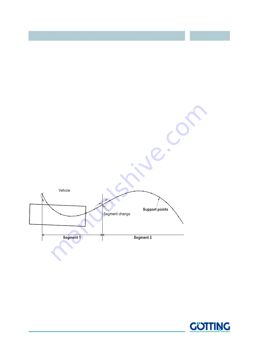
Figure 1
Example: Virtual track with support points
The virtual track consists of several segments that define the sections between
branches and end points. Each of the segments must consist of at least four support
points which are positioned at equal distance over the whole route. These support
points are not actual points on the route (for example transponders in the ground). The
distance between them depends on the type of the route and the vehicle used. The
closer the support points lie next to one another the more precisely the tracking will
correlate with the virtual track. However, very close distances between the points are
unnecessary for large vehicles because the vehicle itself cannot drive that accurately.
Should the distances between the points be too long, the CAD software would display
them as polygonal curves because no rounded curve can be calculated from points
which are wide apart from one another.


