background image

25

CAUTION

E

DGES OF SHEET METAL HOLES MAY BE SHARP. 

U

SE GLOVES AS A

PRECAUTION WHEN REMOVING HOLE PLUGS.

D

IRECT

/S

TANDARD

  I

NLET

  P

IPING

When gas piping enters 

directly

 to the gas valve through the 

stan-

dard

 inlet hole, the installer must supply straight pipe with a ground

joint union to reach the exterior of the furnace.  The rigid pipe must
be long enough to reach the outside of the cabinet to seal the
grommet cabinet penetration.  A semi-rigid connector to the gas
piping can be used outside the cabinet per local codes.

I

NDIRECT

/A

LTERNATE

  I

NLET

  P

IPING

When gas piping enters 

indirectly

 to the gas valve through the

alternate

 gas inlet hole the following fittings (starting from the gas

valve) to reach the outside of the cabinet must be supplied:

Coupling.

90 degree elbow.

2 inch close nipple.

90 degree elbow.

Straight pipe, with a ground joint union, to reach the exterior
of the furnace.  The rigid pipe must be long enough to reach
the outside of the cabinet so as to seal the grommet cabinet
penetration.  A semi-rigid connector to the gas piping can
be used outside the cabinet per local codes.

G

AS

 P

IPING

 C

HECKS

Before placing unit in operation, leak test the unit and gas connec-
tions.

WARNING

T

O AVOID THE POSSIBILITY OF EXPLOSION OR FIRE, NEVER USE A MATCH OR

OPEN FLAME TO TEST FOR LEAKS.

Check for leaks using an approved chloride-free soap and water
solution, an electronic combustible gas detector, or other approved
testing methods.

NOTE:

  Never exceed specified pressures for testing.  Higher

pressure may damage the gas valve and cause subsequent
overfiring, resulting in heat exchanger failure.

Disconnect this unit and shutoff valve from the gas supply piping
system before pressure testing the supply piping system with pres-
sures in excess of 1/2 psig (3.48 kPa).
Isolate this unit from the gas supply piping system by closing its
external manual gas shutoff valve before pressure testing supply
piping system with test pressures equal to or less than 1/2 psig
(3.48 kPa).

P

ROPANE

 G

AS

 T

ANKS


AND

 P

IPING

WARNING

P

ROPANE GAS IS HEAVIER THAN AIR AND ANY LEAKING GAS CAN SETTLE IN

ANY LOW AREAS OR CONFINED SPACES.  

T

O PREVENT PROPERTY DAMAGE,

PERSONAL INJURY, OR DEATH DUE TO FIRE OR EXPLOSION CAUSED BY A

PROPANE GAS LEAK, INSTALL A GAS DETECTION WARNING DEVICE.

A gas detecting warning system is the only reliable way to detect a
propane gas leak. Rust can reduce the level of odorant in propane
gas.  Do not rely on your sense of smell.  Contact a local propane
gas supplier about installing a gas detecting warning system.  If
the presence of gas is suspected, follow the instructions on Page
4 of this manual.

All propane gas equipment must conform to the safety standards
of the National Board of Fire Underwriters, NBFU Manual 58.
For satisfactory operation, propane gas pressure must be 11 inch
w.c. at the furnace manifold with all gas appliances in operation.
Maintaining proper gas pressure depends on three main factors:

1.

Vaporization rate, depending on temperature of the liquid,
and “wetted surface” area of the container or containers.

2.

Proper pressure regulation. (Two-stage regulation is
recommended for both cost and efficiency).

3.

Pressure drop in lines between regulators, and between
second stage regulator and the appliance. Pipe size will
depend on length of pipe run and total load of all appliances.

Complete information regarding tank sizing for vaporization, rec-
ommended regulator settings, and pipe sizing is available from
most regulator manufacturers and propane gas suppliers.
Since propane gas will quickly dissolve white lead and most stan-
dard commercial compounds, special pipe dope must be used.
Shellac-based compounds resistant to the actions of liquefied
petroleum gases such as Gasolac

®

, Stalactic

®

, Clyde’s

®

 or John

Crane

®

 are satisfactory.

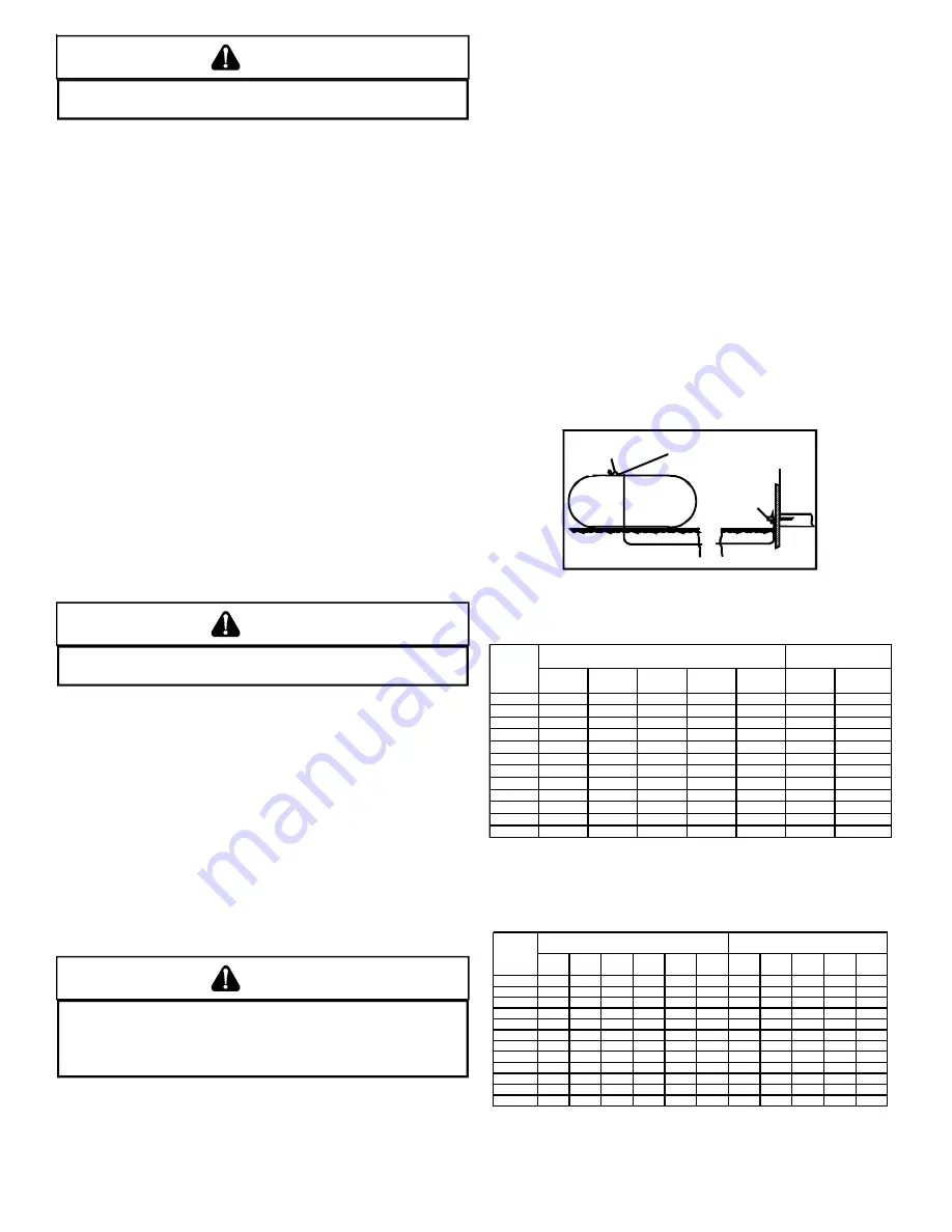
Refer to the following illustration for typical propane gas installa-
tions.

200 PSIG
Maximum

5 to 15 PSIG
(20 PSIG Max.)

Continuous

11" W.C.

Second Stage
Regulator

First Stage
Regulator

Propane Gas Installation (Typ.)

Sizing Between First and Second Stage Regulator*

Maximum Propane Capacities listed are based on 2 psig pressure drop at 10 psig setting.  
Capacities in 1,000 BTU/hour.

Pipe or

Nominal Pipe Size

Tubing

Tubing Size, O.D. Type L

Schedule 40

Length,

3/8"

1/2"

5/8"

3/4"

7/8"

1/2"

3/4"

Feet

10

730

1,700

3,200

5,300

8,300

3,200

7,500

20

500

1,100

2,200

3,700

5,800

2,200

4,200

30

400

920

2,000

2,900

4,700

1,800

4,000

40

370

850

1,700

2,700

4,100

1,600

3,700

50

330

770

1,500

2,400

3,700

1,500

3,400

60

300

700

1,300

2,200

3,300

1,300

3,100

80

260

610

1,200

1,900

2,900

1,200

2,600

100

220

540

1,000

1,700

2,600

1,000

2,300

125

200

490

900

1,400

2,300

900

2,100

150

190

430

830

1,300

2,100

830

1,900

175

170

400

780

1,200

1,900

770

1,700

200

160

380

730

1,100

1,800

720

1,500

To convert to capacities at 15 psig settings - multiply by 1.130
To convert to capacities at 5 psig settings - multiply by 0.879

Propane Gas Piping Chart I

Sizing Between Single or Second Stage Regulator and Appliance*

Maximum Propane Capacities Listed are Based on 1/2" W.C. pressure drop at 11" W.C. setting. 
Capacities in 1,000 BTU/hour.

Pipe or

Nominal Pipe Size

Tubing

Tubing Size, O.D. Type L

Schedule 40

Length,

3/8"

1/2"

5/8"

3/4"

7/8"

1-1/8"

1/2"

3/4"

1"

1-1/4" 1-1/2"

Feet

10

39

92

199

329

501

935

275

567

1,071

2,205

3,307

20

26

62

131

216

346

630

189

393

732

1,496

2,299

30

21

50

107

181

277

500

152

315

590

1,212

1,858

40

19

41

90

145

233

427

129

267

504

1,039

1,559

50

18

37

79

131

198

376

114

237

448

913

1,417

60

16

35

72

121

187

340

103

217

409

834

1,275

80

13

29

62

104

155

289

89

185

346

724

1,066

100

11

26

55

90

138

255

78

162

307

630

976

125

10

24

48

81

122

224

69

146

275

567

866

150

9

21

43

72

109

202

63

132

252

511

787

200

8

19

39

66

100

187

54

112

209

439

665

250

8

17

36

60

93

172

48

100

185

390

590


*Data in accordance with NFPA pamphlet NO. 54

Propane Gas Piping Chart II

Содержание GMS95

Страница 1: ...f in a position which is more hazardous than when the unit is in operation Remember it is your responsibility to install the product safely and to know it well enough to be able to instruct a customer...

Страница 2: ...ROPER VENT FLUE AND COMBUSTION AIR PIPING PRACTICES 13 TERMINATION LOCATIONS 13 CANADIAN VENTING REQUIREMENTS 14 STANDARD FURNACE CONNECTIONS 14 ALTERNATE FURNACE CONNECTIONS 14 NON DIRECT VENT SINGLE...

Страница 3: ...afety Circuit Description 31 GENERAL 31 INTEGRATED CONTROL MODULE 31 PRIMARY LIMIT 31 AUXILIARY LIMIT 31 ROLLOUT LIMIT 31 PRESSURE SWITCHES 31 FLAME SENSOR 31 XVIII Troubleshooting 31 ELECTROSTATIC DI...

Страница 4: ...warranty certificate is also supplied with the unit Read the warranty carefully and note what is covered Keep the warranty cer tificate in a safe location for future reference If additional informatio...

Страница 5: ...lectrical Connection Inlets Alternate 19 Coil Front Cover Pressure Tap 20 Coil Front Cover Drain Port 21 Drain Line Penetrations 22 Drain Trap 23 Blower Door Interlock Switch 24 Capacitor 25 Integrate...

Страница 6: ...are set per the furnace rating plate The input rate and temperature rise are set per the furnace rating plate 100 outside air is provided for combustion air requirements during construction Temporary...

Страница 7: ...ly air opening and the combustible floor Exposure to contaminated combustion air will result in safety and performance related problems Do not install the furnace where the combustion air is exposed t...

Страница 8: ...g system properly vents when tested as outlined above re turn doors windows exhaust fans fireplace dampers and any other gas burning appliance to their previous conditions of use halogen type refriger...

Страница 9: ...input rating of all appliances installed in that space Rooms communicating directly with the space in which the appliances are installed through openings not furnished with doors are considered a par...

Страница 10: ...nsion of rectangular air ducts shall not be less than 3 inches ing shall have a minimum free area of 1 square inch per 1 000 BTU per hour of the total input rating of all gas utilization equipment in...

Страница 11: ...tallation Positions figure for appropriate in stallation positions ductwork connections and resulting airflow arrangements VII HO VII HO VII HO VII HO VII HORIZO RIZO RIZO RIZO RIZONT NT NT NT NTAL AP...

Страница 12: ...ane gas installations require an orifice change to compensate for the energy content difference between natural and propane gas High altitude installations may require both a pressure switch and an or...

Страница 13: ...nt flue pipe and a combustion air intake pipe Refer to the appropriate section for details concerning piping size length number of elbows furnace connections and terminations MATERIALS AND JOINING MET...

Страница 14: ...DIRECT VENT INSTALLATIONS On upflow units secure the combustion air intake pipe directly to the air intake coupling On counterflow units secure the combus tion air intake pipe to the air intake coupl...

Страница 15: ...ue piping to the rubber elbow using a worm gear hose clamp NOTE Use of the alternate vent flue location for upright installations requires the drain trap be installed on the same side of the unit as t...

Страница 16: ...ould be in stalled on either side of the wall and solvent cemented to a length of pipe connecting the two couplings The length of pipe should be the wall thickness plus the depth of the socket fitting...

Страница 17: ...s in each Vent Flue Combustion Air Intake pipe Elbows and or tees used in the terminations must be included when determining the number of elbows in the piping systems If the combustion air intake pip...

Страница 18: ...es If the pipes must go below the joist and then up into the last joist space to penetrate the header two 45 elbows should be used to reach the header rather than two 90 elbows VENT INTAKE TERMINATION...

Страница 19: ...t installations using the standard vent flue outlet require drain hoses to be connected as follows The following quantity of hoses tubes and hose clamps are provided with the unit HOSE A QTY 1 HOSE B...

Страница 20: ...flow models relocation of the front cover pressure switch hose is required Make connections as follows 1 Remove the rubber plug from the coil front cover drain port Counterflow furnaces Relocate the f...

Страница 21: ...is an integral part of this furnace Field alter ation to comply with electrical codes should not be required Wires are color coded for identification purposes Refer to the wiring diagram for wire rout...

Страница 22: ...at 120 VAC Turn OFF power to the furnace before installing any accessories Follow the humidifier or air cleaner manufacturers instructions for locating mounting grounding and controlling these access...

Страница 23: ...field convertible for use with propane gas by replacing the regulator spring with a propane gas spring from an appropriate manufacturer s propane gas conversion kit Taps for measuring the gas supply p...

Страница 24: ...rotect against external corrosion when in contact with masonry plaster or insulation or subjected to repeated wetting by liquids such as water except rain water detergents or sewage MANUAL SHUT OFF VA...

Страница 25: ...nace manifold with all gas appliances in operation Maintaining proper gas pressure depends on three main factors 1 Vaporization rate depending on temperature of the liquid and wetted surface area of t...

Страница 26: ...the dampers or other means used to control the flow of air must be adequate to prevent chilled air from entering the furnace and if manually operated must be equipped with means to prevent operation...

Страница 27: ...nace is equipped with an ignition device which automatically lights the burner Do not try to light the burner by hand 5 Move the furnace gas valve manual control to the OFF position 6 Wait five minute...

Страница 28: ...soap suds check for leaks at hose connection Bubbles forming indicate a leak SHUTOFF GASAND FIXALLLEAKS IMMEDIATELY BEFORE PROCEEDING TO NEXT STEP 6 Measure furnace gas supply pressure Supply pressure...

Страница 29: ...uals the installation s gas heating value multiplied with a conversion factor hours to seconds divided by the number of seconds per cubic foot The measured input must not be greater than the input ind...

Страница 30: ...sensed Circulator blower is energized on heat speed following a fixed thirty second blower on delay Electronic air cleaner terminals are energized with circulator blower Furnace runs integrated contro...

Страница 31: ...DISCHARGE ESD PRECAUTIONS NOTE Discharge body s static electricity before touching unit An electrostatic discharge can adversely affect electrical components Use the following precautions during furna...

Страница 32: ...e filter s by reversing the procedure for removal 4 Turn ON electrical power to furnace MEDIA AIR FILTER OR ELECTRONIC AIR CLEANER REMOVAL Follow the manufacturer s directions for service BURNERS Visu...

Страница 33: ...he blower until filter clears bottom rail 5 Lower filter down and pull outward Front of Furnace Blower Front of Furnace Blower 6 Replace filter by reversing procedure X X X X XXI BEFO XI BEFO XI BEFO...

Страница 34: ...34...

Страница 35: ...kage proper length elbows and termination Check drain system Correct as necessary Correct pressure switch setpoint or contact motion Tighten or correct wiring connection Pressure switch hose blocked p...

Страница 36: ...e sensor with emery clot See Vent Flue Pipe section for piping details See rating plate for proper gas pressure 7 7 FLASHES Flame sensor is coated oxidized Flame sensor incorrectly positioned in burne...

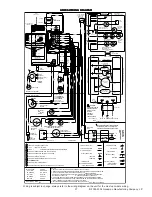
Страница 37: ...OSTAT CONNECTIONS BU GN GND 115 VAC 24 VAC BLOWER COMPARTMENT DOOR SWITCH OPEN WHEN DOOR OPEN DOOR SWITCH WARNING DISCONNECT POWERBEFORE SERVICING WIRING TOUNITMUST BE PROPERLYPOLARIZED AND GROUNDED B...

Отзывы: