background image

HS-50 & HS-100 

Doc. No 1199-PS-0035 Issue 3 

June 2021 

___________________________________________________________________________________________ 


Page 51 


18  MAINTENANCE & FAULT-FINDING 


18.1 Cleaning 

If there is any build-up of deposit on the unit, it should be gently cleaned with a cloth moistened with 
water and soft detergent. Solvents should not be used, and care should be taken to avoid 
scratching any surfaces. The unit must be allowed to defrost naturally after being exposed to snow 
or icy conditions, do NOT attempt to remove ice or snow with a tool.  
   

18.2 Servicing 

There are no moving parts or user-serviceable parts requiring routine maintenance. 
Opening the unit or breaking the security seal will void the warranty and the calibration. 
In the event of failure, prior to returning the unit to your authorised Gill distributor, it is 
recommended that: 

1.  All cables and connectors are checked for continuity, bad contacts, corrosion etc. 

2.  A bench test is carried out as described in Section 19.1. 

3.  You contact your supplier for advice 

18.3 Fault-finding 


Symptom 

Solution 

No output 

Check DC power to HS, cable and connections. 
Check comms settings of R3 (

as detailed in Section 14)

 and host system 

match, including correct Com port.  
Check unit is in Continuous mode  
Check that in-line communication devices are wired correctly. 
NOTE: It is usual for Anemometer TX to be connected to converter device RX  

Corrupted output 

Check comms settings of HS and host system match. 
Try a slower baud rate. 
Check cable lengths and type of cable. 

One way 
communication 

Check HS and host system are both set to the same protocol (RS232 for PCI, 
RS422 for direct connect to HS). 
Check wiring is in accordance with the manual. 

Failed / Incorrect 
WindMaster output, 
data invalid flag 

Check that transducer path is not blocked 

18.4 Status (error) codes 


Refer to section 14.2.


18.5 Returning units 


If the unit has to be returned, it should be carefully packed in the original packaging and returned to 
your authorised Gill distributor, with a full description of the fault condition.   
 

19  TESTS 


19.1 Bench test 

1.  Couple the HS to the host system and power supply, using a known working test cable. 

2.  Check that the unit is correctly configured. 

3.  Check for normal output data, and that the Status Code cycles through 01 to 10.  

4.  If the status code is 00, refer to Section 14.2 Status Fields. 

5.  Use an office fan or similar to check that the unit is sensing wind, turning the unit to simulate 

changing wind direction and to check that all three axes are functioning. 

6.  Note that this a quick functional test. There are no calibration adjustments.  

See 18.2.


Содержание 1199-PK-085

Страница 1: ......

Страница 2: ... 15 8 13 Default Configuration Command Settings 15 8 14 Default Output Data String 15 8 15 Interrogation Commands 15 9 CONNECTION TO A PC OR OTHER DEVICE 16 9 1 Anemometer Connector SIU Power and Data Connector 16 10 CONNECTING AN HS UNIT TO A PC USING RS 422 17 10 1 Connecting an HS Unit to a PC via Power and Communications Interface PCI 1189 PK 021 or PCIA 1189 PK 020 17 10 1 1 Environmental 17 ...

Страница 3: ...15 2 Analogue outputs 41 15 3 Analogue Sync Output 42 15 4 Analogue Status Output 42 15 5 Test Modes 42 16 VIEWING LOGGING THE DATA USING GILL WINDVIEW SOFTWARE 43 17 INSTRUCTIONS FOR USING WINDCONVERT BINARY TO ASCII CONVERSION UTILITY 49 18 MAINTENANCE FAULT FINDING 51 18 1 Cleaning 51 18 2 Servicing 51 18 3 Fault finding 51 18 4 Status error codes 51 18 5 Returning units 51 19 TESTS 51 19 1 Ben...

Страница 4: ... as a general term for both the HS 50 HS 100 they are robust three axis anemometers with no moving parts The units of wind speed output rate and formats are all user selectable Both the HS 50 HS 100 are constructed of stainless steel can perform measurements in wind speeds up to 45m s The HS 50 can provide an output rate up to 50Hz and the HS 100 can provide an output rate up to 100Hz Each unit is...

Страница 5: ...e Connector 020 01559 Power Communications Interface incl Analogue 1189 PK 020 Flight Case 1210 30 074 4 way Connector 020 00978 Mains Lead 026 00244 Plug 10 Pin Round 020 00290 Plug 8 Pin Round 020 00291 4 OPTIONAL EXTRAS Item Part Number Power Communications Interface PCIA Anemometer Power Supply Communications including Analogue Digital Outputs 1189 PK 020 Power Communications Interface PCI Ane...

Страница 6: ...ther upper and lower transducers As Figure 1 shows the air velocity along the axis between each pair of transducers can then be calculated from the times of flight on each axis This calculation is independent of factors such as temperature From the three axis velocities the wind speed is calculated as either signed U V and W or as Polar and W It can be seen from Figure 1 that the speed of sound in...

Страница 7: ... Altitude 0 to 3000m 0 to 3000m Moisture Dust Protection IP65 IP65 Humidity 5 to 100 5 to 100 Precipitation Operation up to 300 mm hour Operation up to 300 mm hour EMC Emissions BS EN 50081 1 1992 Immunity BS EN 50082 1 1992 Emissions BS EN 50081 1 1992 Immunity BS EN 50082 1 1992 Input Output Protection 0 8J 0 8J Serial Interface Electrical Interface Full Duplex RS422 Full Duplex RS422 Baud Rates...

Страница 8: ...ers from damage distortion as this will affect the accuracy of the measurements made The transducers should not be used to support the weight of the frame if it is rested on a flat surface such as a table as this will distort the path lengths The protective head cover should be left on under these circumstances When handling the frame ensure that it is picked up by the main arm not the frame aroun...

Страница 9: ...should not be created wire the system in accordance with the installation guidelines Ensure the power supply operates to the HS specification at all times Avoid turbulence caused by surrounding structures that will affect the accuracy of the HS such as trees masts and buildings The World Meteorological Organisation makes the following recommendation The standard exposure of wind instruments over l...

Страница 10: ...ection of 90 anti clockwise from N the Reference spar W is defined as vertically up the mounting shaft Note when the unit is configured for the ALIGN AXIS setting the UV definition rotates 30 degrees anti clockwise such that U is now in line with transducer axis 1 7 6 Alignment Dimensions Orientation It is recommended that the head is aligned so that the upper transducer sphere is directly above t...

Страница 11: ...trical noise 7 9 Corrosion Galvanic corrosion is possible unless stainless steel fixings are used for mounting the head and electronics unit This will ensure that the anemometer will provide long service in extreme conditions such as a marine environment for example 7 10 Earthing For maximum protection against lightning the anemometer must be earthed via its mountings The Electronics unit and PCI ...

Страница 12: ...74 91009 The cable allows for the connection of all Power inputs Digital data inputs and outputs Other example twisted pair screened cable types 24AWG are No of pairs Gill ref Belden ref Batt electronics ref 2 9729 3 026 02660 9730 91030 4 026 03156 9728 91199 6 9731 91031 7 12Cable length The maximum cable length is dependent on the chosen communication format RS232 RS422 or RS485 the baud rate a...

Страница 13: ...irose Pin Number Designation 1 Reserved 2 RS422 Tx 3 RS422 Tx 4 RS422 Rx 5 RS422 Rx 6 Supply ve 7 Reserved 8 Reserved 9 Chassis 10 Anemometer Sync 11 Not Connected 12 Not Connected 13 Digital 0v 14 Supply ve 15 Reserved 16 Reserved 17 Reserved 18 Anemometer Sync 19 Reserved 20 Reserved Assembly of the 20 way Hirose connector is shown below The outer sheath needs to be cut back by 45mm and the indi...

Страница 14: ...lt mode from power up 2 Interactive mode This allows the anemometer to be configured and interrogated 8 3 Measurement Mode The principle of operation is described in Section 5 page 5 The parameters sampled are determined by the anemometer s configuration and consist of 1 Wind velocity axis velocities are always sampled 2 Speed of Sound SoS 3 Analogue Inputs 6 4 Absolute Temperature PRT100 The way ...

Страница 15: ...e following formats 1 Absolute Temperature K 2 Absolute Temperature C Absolute temperature measurements can be disabled 8 7 Analogue Input Reporting Formats If ASCII format is selected analogue input measurements are output in volts to 4 decimal places If binary format is selected analogue input measurements are output in 2 s complement The number of analogue inputs to be measured can be set from ...

Страница 16: ... Command Settings Factory settings are AVERAGE 5 WINDREP UVW CAL SOSREP SONICTEMP K ABSTEMP OFF ANAIP DDDDDD DISABLED AOPFSD 30 POLARWRAP 360 STRFMT ASCII UNPAD ASCTERM CRLF ECHO ON MSGMODE CONT BAUD 9600 CTONE ON ALIGN AXIS INST OFF 8 14Default Output Data String The Structure of the Factory HS Default Output Data String is as follows Status Codes U V W Speed of Sound Checksum 01 08 00 01 00 00 0...

Страница 17: ...s data in RS422 format which can be reconstituted to analogue via the optional PCIA Baud rate options are 1 2400 2 4800 3 9600 4 19200 5 38400 6 57600 7 115200 Note if changing a unit to 115200 Baud rate ensure that the connecting device supports 115200 baud e g RS422 converter PC Laptop etc Data format 8 data 1 stop no parity 9 1 Anemometer Connector SIU Power and Data Connector Hirose 20 way soc...

Страница 18: ...perated with the Power and Communications and Interface unit PCI or Analogue Output version PCIA which can be ordered as an optional extra Connect HS via RS422 port then connect computer to RS232 port on PCI PCIA HS 20 Way Connector PCI 15 Way D Type Connector PCI RS232 9 Way D Type Connector Computer 9 Way D Type Connector Signal Names Pin No s Pin No s Signal Name Signal Name Pin No s Pin No s S...

Страница 19: ...outputting RS422 data correctly If the PCI PCIA RS 232 connection is connected to a computer then when a terminal programme is opened and commands sent by a PC keypad or program to the box its TX LED will illuminate intermittently indicating a good connection between the PC and the box Connector Pin and Cable Assignments for PCI PCIA are as follows Anemometer Connector 15 Way RS232 Output 9 way Pi...

Страница 20: ...HS 50 HS 100 Doc No 1199 PS 0035 Issue 3 June 2021 ___________________________________________________________________________________________ Page 19 Assembly of Amphenol C91A Screw Lock Socket ...

Страница 21: ...3 17 Analogue Output 4 18 Analogue Output 5 19 Analogue Output 6 20 Analogue Output 7 21 Analogue Output 8 22 Test Pin 2 23 Earth 24 Status Output 25 Sync Output The analogue outputs have the following specification Full scale range 2 5v to 2 5v Accuracy 0 25 of full scale 9 bits Resolution 14 bits over 3 0v Settling time 2ms to 0 25 accuracy note that the minimum time between samples is 10ms Outp...

Страница 22: ...___________________________________________________________________________________ Page 21 10 1 5 Gill Instruments HS to PCI A Ready Made Gill Cable 1210 PK 043 The optional 1086 10 043 cable allows for connection between either the PCI PCIA and HS or the SIU ...

Страница 23: ...HS 50 HS 100 Doc No 1199 PS 0035 Issue 3 June 2021 ___________________________________________________________________________________________ Page 22 ...

Страница 24: ...HS 50 HS 100 Doc No 1199 PS 0035 Issue 3 June 2021 ___________________________________________________________________________________________ Page 23 11 SYSTEM CONNECTION DIAGRAMS 11 1System Connection ...

Страница 25: ... 2021 ___________________________________________________________________________________________ Page 24 11 2 1199 00 015 Interface Cable The 1 5 metre 1199 00 015 cable supplied allows for connection between the HS Frame and the Electronics Unit ...

Страница 26: ...Unit and to take analogue data from that equipment The anemometer digitises the analogue data and appends it to the digital data string A sensor supply voltage is available at each connector The voltage at this connector is the supply voltage at the HS Electronics Unit minus 1 5 volts The sensor supply voltage is internally regulated to 21 2 volts for SIU supply voltages above 22 volts For sensors...

Страница 27: ...PRT conforming to IEC 751 or DIN 43760 Compatibility with other standards may be available on request PRT connector pin out 1 Sensor power 2 Analogue input 6 3 Analogue input 6 4 Analogue ground 5 PRT excitation 6 PRT excitation 7 PRT sense 8 PRT sense 9 Sensor power 10 Chassis screen PRT connection diagram PRT excitation PRT sense PRT 100 PRT sense PRT excitation For correct operation the PRT con...

Страница 28: ...HS 50 HS 100 Doc No 1199 PS 0035 Issue 3 June 2021 ___________________________________________________________________________________________ Page 27 12 3Electronics Unit Mounting Details ...

Страница 29: ...Wind is a software package from Gill Instruments that is free to download from the Gill Instruments website http gillinstruments com main software html It is primarily designed for use with the WindSonic and WindMaster range of anemometers but it is possible to use as a terminal package to communicate with the HS The tool features are not applicable To begin open the Wind software and select the r...

Страница 30: ...______________________________________________________________________ Page 29 Click on the Baud rate menu and select the required Baud rate to match the HS unit Data will start scrolling in the terminal window assuming that the HS is configured to output in Gill ASCII mode ...

Страница 31: ...e with the exception of the enter interactive mode command and polled data request command ASCII Output String Termination The ASCII output string terminator can be configured to be either CR or CR LF The expression TERM is used to indicate either one of these string terminators Character Echo Character echo can be enabled or disabled If enabled received characters are only echoed while in interac...

Страница 32: ...ces are optional n m Repeat the symbols inside the braces can be repeated n to m times If n is not included then 0 is implied if m is not present then infinity is implied Non literal symbol this represents other non literal and literal symbols A further definition is required to define this non literal symbol Note Parameters in bold are the default settings Syntax followed by sending CR LF pressin...

Страница 33: ...ackage must be changed to that of the new setting for the HS any delay may result in an error message Confirm b CR VBAUD HS exit Note In general the more parameters required in the output data string and the faster the output rate the higher must be the Baud rate to get a fully reported data string or change a parameter setting CONFIG Syntax CONFIG Description Reports the anemometer s configuratio...

Страница 34: ...ported as speed SONICTEMP SOS is reported as sonic temperature K Sonic temperature reporting in K C Sonic temperature reporting in C Example HS SOSREP SONICTEMP C CR VSOSREP STRFMT Syntax STRFMT BINARY ASCII PAD UNPAD Description Sets the result message string format Parameters BINARY Binary result message format ASCII ASCII result message format PAD ASCII fields padded to fixed size padded with 9...

Страница 35: ...nd Component Fields UVW format Wc1 U axis velocity in 0 01ms 1 units Two s complement signed Wc2 V axis velocity in 0 01ms 1 units Two s complement signed Wc3 W axis velocity in 0 01ms 1 units Two s complement signed Polar format Wc1 U V plane velocity direction in relative to N Wc2 U V plane velocity magnitude in 0 01ms 1 units Wc3 W axis velocity in 0 01ms 1 units Two s complement signed Axis Sp...

Страница 36: ...s are defined as follows Wind Component Fields UVW format Wc1 U axis velocity in 0 01ms 1 units UU UU Wc2 V axis velocity in 0 01ms 1 units VV VV Wc3 W axis velocity in 0 01ms 1 units WW WW Polar format Wc1 U V plane velocity direction in relative to N DDD Wc2 U V plane velocity magnitude in 0 01ms 1 units MM MM Wc3 W axis velocity in 0 01ms 1 units WW WW Axis Speeds Wc1 Ultrasonic axis 1 velocity...

Страница 37: ...put cycles through the status codes 01 10 at each output sample If the anemometer detects an error then the status code 00 is displayed instead of the next cyclic status code When the error is cleared the status codes will continue to cycle from where they were interrupted If the error is caused by a transducer pair failure then the error code is displayed until the failure is rectified If the err...

Страница 38: ...utput configuration 1 Bits 1 0 00 Wind mode UVW 01 Wind mode axis 10 Polar 360 wrap 11 Polar 540 wrap Bits 3 2 00 10ms 1 Full Scale Deflection 01 20ms 1 Full Scale Deflection 10 30ms 1 Full Scale Deflection 11 60ms 1 Full Scale Deflection Bits 5 4 00 SOS report off 01 SOS report speed of sound 10 SOS report sonic temp K 11 SOS report sonic temp C Bits 7 6 00 PRT temp off 01 PRT temp K 10 PRT temp ...

Страница 39: ...he error history is cleared when the user enters interactive mode Address 05 Transducer gain levels Bits 1 0 00 Channel pair 1 nominal 01 Channel pair 1 50 10 Channel pair 1 90 11 Channel pair 1 100 Bits 3 2 00 Channel pair 2 nominal 01 Channel pair 2 50 10 Channel pair 2 90 11 Channel pair 2 100 Bits 5 4 00 Channel pair 3 nominal 01 Channel pair 3 50 10 Channel pair 3 90 11 Channel pair 3 100 Bit...

Страница 40: ...eter y axis MSB 10 inclinometer y axis LSB The above data are output as 16 bit twos complement numbers In ASCII output format two hex characters are output for each status address Sb Status Data For the conditions when Sa 07 10 Then Sb gives Inclinometer data as 16 bit twos complement numbers expressed with two hex characters All these hex values should first be translated into decimal values Then...

Страница 41: ... positive and negative y values are as illustrated below U U axis velocity in 0 01 m s unit V V axis velocity in 0 01 m s unit W W axis velocity in 0 01 m s unit ST C Sonic temperature in 0 01 degree C unit Inclinometer data in degrees can be obtained by placing the unit into Interactive Mode IM and typing INCL the unit will report the inclination of the Anemometer The Format is XX XX YY YY If an ...

Страница 42: ...Output voltage V 2 5 0 833 0 0 833 2 5 360 180 0 180 540 0 180 360 540 The 540 mode avoids the output oscillating between 2 5V and 2 5V in response to a direction varying around 180 Channel 4 Speed of Sound or Sonic Temperature The variable represented by this analogue output also depends on the configuration of the anemometer s speed of sound or sonic temperature The representations for each avai...

Страница 43: ...f the 25 way D type connector on the PCIA indicates that the analogue outputs are valid i e the full set of configuration data have been received from the anemometer and there are no data errors for the current output data The pin assignment and electrical specification of the status output are contained in Section 10 1 4 15 5Test Modes The analogue output system includes two self test modes They ...

Страница 44: ...at is free to download from the Gill Instruments website http gillinstruments com main software html It is designed to allow the user to view and log data from a single or multiple anemometers Please note that WindView does not allow 2 way communication with the connected anemometer so any configuration of the HS must take place prior to connection to WindView To begin open the WindView software p...

Страница 45: ..._______________________________ Page 44 Select Connect from the File Drop down menu The Output Format field should match the sensor ie Gill Polar 3 axis UV or NMEA Select the required COM Port from the menu Select the required baud rate to match the sensor eg 9600 baud Leave Parity set for None Click on Connect ...

Страница 46: ...Doc No 1199 PS 0035 Issue 3 June 2021 ___________________________________________________________________________________________ Page 45 Data should scroll on screen To Log data use Settings menu and select logging ...

Страница 47: ...____________________________________________________________________________ Page 46 Select type of log in this case continuous with boxes ticked for append time stamp and append record count if required Select a file directory and file name Click on Apply Click on OK ...

Страница 48: ... No 1199 PS 0035 Issue 3 June 2021 ___________________________________________________________________________________________ Page 47 To Start the Logging Select File Log Start To Stop the Logging Select File Log Stop ...

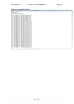
Страница 49: ...HS 50 HS 100 Doc No 1199 PS 0035 Issue 3 June 2021 ___________________________________________________________________________________________ Page 48 Example HS data logged Notepad ...

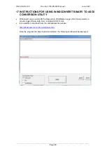
Страница 50: ...NG WINDCONVERT BINARY TO ASCII CONVERSION UTILITY WinConvert can be used with the Research WindMaster range of Gill Anemometers to convert logged Binary data into a readable ASCII format It is available to download from the Gill Instruments website http gillinstruments com main software html Once the program has downloaded and started the following window will be displayed ...

Страница 51: ...ter type is unknown click begin to start the process and the following window will be displayed Select open and the conversion process begins once complete the following message will be displayed The results will be displayed in the main program lower window together with the field information for the string To save the data select all the text in the lower window copy it Then open up a notepad wo...

Страница 52: ...ncluding correct Com port Check unit is in Continuous mode Check that in line communication devices are wired correctly NOTE It is usual for Anemometer TX to be connected to converter device RX Corrupted output Check comms settings of HS and host system match Try a slower baud rate Check cable lengths and type of cable One way communication Check HS and host system are both set to the same protoco...

Страница 53: ... value being output by the HS These values should be within 3 C of each other within the temperature range specified above If the Sonic Temperature reports outside of this tolerance range the HS has potentially suffered head distortion If this is the case the HS will need to be returned to Gill Instruments for investigation 19 3Calibration Note There are no in use calibration adjustments the unit ...

Страница 54: ... 53 20 APPENDIX A Summary Of Abbreviations Used In This Manual ASCII American Standard Code for Information Interchange PCIA Power Communications Interface with Analogue Outputs PCI Power Communications Interface SIU Sensor Input Unit PRT Platinum Resistance Thermometer RS232 Communications standard RS422 Communications standard SoS Speed of Sound ...

Отзывы: