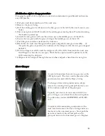
Ducting
LFGI Venting Options
The new NIOSH and USP <797> regulations have made it necessary that the airflow design
of barrier isolators be flexible to accommodate a variety of conditions.
For example, it is recommended that a safety cabinet used in the handling of hazardous
drugs does not recirculate air within the work area. The potential vaporization of the
hazardous material is of concern. The recirculated air is HEPA filtered but this filtration
removes particulate only, not vapors. The recirculation of this vapor- laden air serves only
to concentrate vapors within the work area thereby increasing the potential for worker
exposure. To meet this recommendation the LFGI can be configured to totally exhaust all
air from the work area. This requires the facility to provide a blower that is capable of
moving 300-600 cfm through an 8” diameter duct. (LFGI exhaust volume depends upon the
size of the unit. 3 foot units exhaust 300 cfm, 4 foot units 400 cfm and 6 foot units 600
cfm.) Static pressure in this situation can range from 0.05 if the exhaust blowers are left on
to upwards of 2” w.c. if the exhaust blowers are turned off and the HEPA filter is
moderately loaded with particulate. Ensure static capacity of the external blower can also
accommodate the static imparted by the ducting used. The LFGI has a height adjustable
stand and to retain this feature we recommend that the portion of ducting immediately
exiting the LFGI be a flexible duct of at least 10 inches of length.
The standard LFGI configuration requires no venting. The HEPA filtered exhaust air is
recycled by an external clean air plenum up the rear of the unit back to supply air intake. A
small amount of HEPA filtered air is exhausted out of the unit into the surrounding room.
Electronic Adjusting Stand
The electronic height adjusting stand is powered by a motor housed at the back of the LFGI.
Hydraulic lines run to a cylinder at each caster and are pressurized to move the work area up
and released to lower it. This action is activated by a switch located under the work area on
the outside of the unit. Direction is indicated by arrows on the switch.
The electronic adjusting stand requires its own power outlet/plug.
31
Содержание LFGI-3USP
Страница 1: ...Laminar Flow LFGI CAI or CACI User Manual ...
Страница 33: ...33 ...
Страница 51: ...SECTION IV UNIT DIAGRAM Made in the USA and available for purchase on the GSA 51 ...
Страница 55: ...55 ...
Страница 59: ...59 ...
Страница 63: ...Fig 2 Air recycle plenum connection tip removed 63 ...
Страница 85: ... 863 248 2800 www sensocon com 20 Installation and Operation Manual Series A3 A4 ...


