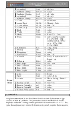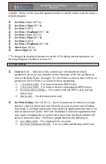
Basic Operation
Supply air is brought into the unit through the top prefilters and directed through the Supply
HEPA filter by a series of backwards-inclined motorized impellers. This unidirectional air
moves downward to the work deck then splits to the front and back air grills. Then moves
under the work tray and through the exhaust HEPA filter. Next the air is forced by a
second set of backwards-inclined motorized impellers up an external air recycle plenum. At
the top, air being recycled is split between a 4” duct collar and recycling tip, which directs
the recycled air under the prefilters and the cycle continues. Optional Exhaust tips allow for
100% exhaust of air after it passes through the Exhaust HEPA filter, this connection is via
an 8” exhaust connection.
Airflow Set Up
To set airflow if work-area is over or under pressure as indicated by digital pressure gauge,
unplug the cord going to the exhaust blower, located on the lower rear side of the LFGI and
adjust supply speed control, located on the rear of the control panel. For positive pressure
operation set supply HEPA filter pressure gauge to 0.50“ H
2
O, for negative pressure set
gauge to0.35” H
2
O for negative pressure unit. Next reconnect exhaust blowers and adjust
exhaust speed control, located on the rear of the control panel, to set digital pressure gauge
to the proper work-area pressure as indicated above. If further adjustments to the velocity
are required, a clockwise adjustment of either speed control will always increase air velocity
while each one will have an opposite effect on the work-area pressure. A counterclockwise
adjustment (increase motor speed) of the exhaust blowers will lower overall unit pressure
while increasing velocity and a clockwise adjustment (decrease motor speed) will lower
velocity while increasing work-area pressure. For the supply blower a counterclockwise
adjustment (increase motor speed) of the exhaust blowers will increase overall unit pressure
while increasing velocity and a clockwise adjustment (decrease motor speed) will lower
velocity while decreasing work-area pressure.
Isolator Pressure
Work-area can be positive or negative pressure depending on the customer’s desired bias to
either clean environment or containment. In either mode the unit provides unidirectional
airflow and an ISO class 5 or better air quality. Pressurization should be set to positive (+)
0.09 to 0.125 or negative (-) 0.09 to 0.125, inches of water on the digital pressure gauge
marked work-area pressure. This overall pressure will provide greater than 100 fpm into or
out of the LFGI USP in the event of a complete glove and sleeve failure, approximately 70
cfm.
Supply Velocity
Average Velocity Range: 45-55 fpm average, all /- 25%.
Where: 12” below Diffuser
61
Содержание LFGI-3USP
Страница 1: ...Laminar Flow LFGI CAI or CACI User Manual ...
Страница 33: ...33 ...
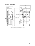
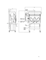
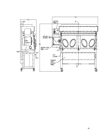
Страница 51: ...SECTION IV UNIT DIAGRAM Made in the USA and available for purchase on the GSA 51 ...
Страница 55: ...55 ...
Страница 59: ...59 ...
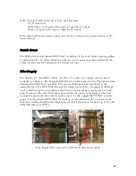
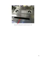
Страница 63: ...Fig 2 Air recycle plenum connection tip removed 63 ...
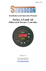
Страница 85: ... 863 248 2800 www sensocon com 20 Installation and Operation Manual Series A3 A4 ...

