Operation Manual for ZBL-R620/R630 Rebar Locator
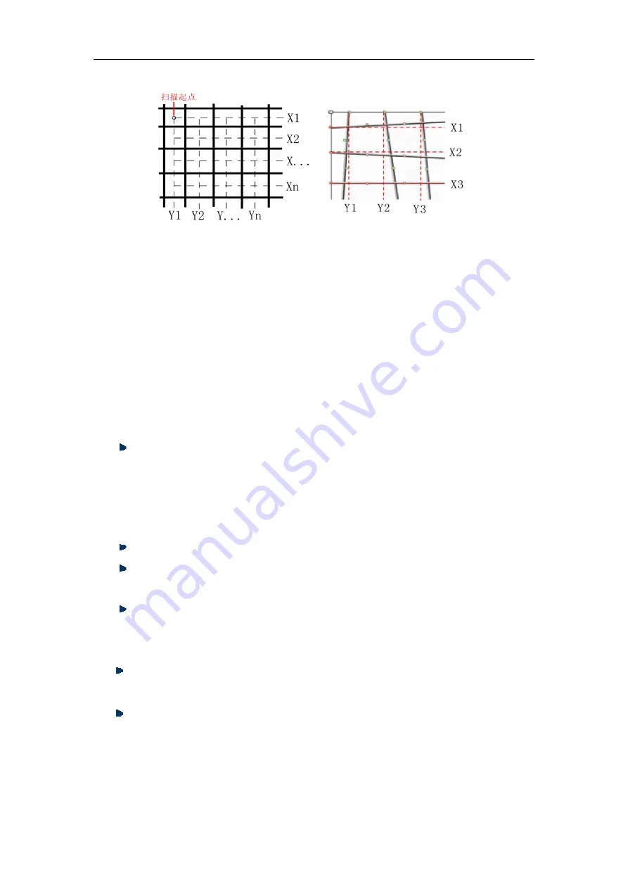
Second scan updates scan data only, doesn’t update the rebar’s distribution image.
The second scan operation introduced above is the normal operation, users don’t
need to scan every adjacent bar, instead a cross-bar scan is performed. For the Cross-bar
scan a single bar in the x-direction and a single bar in the y-direction are selected for use
during a second-scan operation. In order to use Windows software analysis the operator
is required to record the separation between the parallel test lines of the first and second
scans. For queries related to the use of the Windows software, the reader is directed to
the R650 software operation manual.
2.7 Data Display
Display the saved component, data and image
1) In Menu interface, move the cursor to “data display” option.
Press
【
Enter
】
to access the “components list” interface
2) In data display interface
The left column shows the “components list”, listed in descending order with the newest at
the top. The right column shows the “data display” area, displaying the statistical
information of saved data for the current concrete element.
【↑
,
↓】
keys, move cursor to the concrete element you want to select.
【←
,
→】
keys, allow movement to the next or previous pages of “concrete
elements menu” shown in the left column of the screen;
Press
【
Menu
】
key, return to main menu.
Press
【
Enter
】
key to access the data display interface, the screen displays data or image
(profile, grid).
【↑
,
↓】
key, allow movement to previous or next page in up-down direction
(profile or grid scan mode);
【 ←
,
→ 】
key, allow movement to previous or next image in left-right
direction(profile or grid scan mode).
2.8 Data Transmission
Using data transmission any data saved within the appliance can be transferred to an
Fig. 2.9
Fig. 2.10


