background image

MA-041 

 DGA 900 Plus - Installation & Commissioning Manual - Rev 1.1 

4-Mar-22 

Page 80 of 99 

3.


Type a meaningful name for the database e.g. 

[DGA900_PLUS_SERIAL_NUMBER]_[DATE & 
TIME]_COMMISSIONING_[CUSTOMER_NAME]


4.


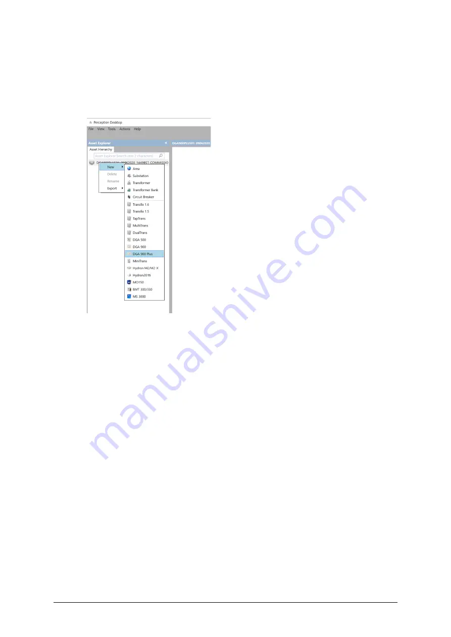
In the Asset Explorer, right click on the newly created database and select 

New > 

DGA 900 Plus

 as shown in Figure 10-11. 


Figure 10-11: New > DGA 900 Plus database 

5.


On the Properties tabbed page, enter the connection details. 

6.


If a successful connection is made, a green tick appears on the DGA 900 Plus icon 
in the Asset Hierarchy. 

7.


Right click the DGA 900 Plus icon and select 

Download

 from the shortcut menu. 

8.


On the Properties tabbed page, the Device Connection details should show the 

State as ‘Connected’ and actively display the download in progress.


9.


Once the download completes, select the 

Data Table

 tab. 

9. 

In the Data Table tabbed page, right click in the data area and select 

Add/Remove 

Measurement Points

11. Select 

Tap Position

 and 

OLTC Motor Torque 

as shown in Figure 10-12. 

Note: 

All other options should be left unchecked. 

Содержание Kelman DGA 900 Plus

Страница 1: ...GEDE GA_M DLIS TE MA 041 Rev 1 1 4 Mar 22 GE Grid Solutions Kelman DGA 900 Plus Transformer Monitoring System Installation Commissioning Manual ...

Страница 2: ...rement 26 8 2 Motor Power Converter 30 9 Card Option 4 Bushing PD Monitor 33 9 1 Installation Layout 33 9 2 Inside the Hub Module 34 9 3 Power Communications 36 9 4 Bushing Adaptors 36 9 4 1 Bushing Adaptor Cables 37 9 4 2 Install a Bushing Adaptor 44 9 5 High Frequency Current Transformer HFCT 47 9 6 Magnetically Mounted Temperature Sensors 50 9 7 Cabinet Connections 52 9 7 1 Bushing Adaptors Neu...

Страница 3: ...0 4 4 C 4 Tan δ Power Factor Measurement 89 10 4 5 PD Live HF Noise Threshold Measurement 90 10 4 6 PDI Associated Power Measurement 91 10 4 7 PD Average Apparent Charge Measurement 92 10 4 8 PD Max Apparent Charge Measurement 92 10 4 9 Export Setting 94 10 4 10Finalisation 95 Parts and Tools List for Bushing PD monitor 96 A 1 GE supplied items shipped with the product 96 A 2 GE Field Service Engi...

Страница 4: ...le 31 Figure 9 1 General installation layout single transformer 34 Figure 9 2 General installation layout bank of 3 single phase transformers 34 Figure 9 3 Hub module 35 Figure 9 4 Hub module with Thermal Models and Bushing Monitor cards 35 Figure 9 5 Bushing Adaptor without top cover 37 Figure 9 6 Bushing Adaptor with top cover 37 Table 9 1 GE supplied materials 38 Table 9 2 Customer supplied too...

Страница 5: ...63 Figure 9 44 Save As AdaptorOnly 64 Figure 9 45 Save As AdaptorInstalled 64 Figure 9 46 AntScope measurement AdaptorInstalled 65 Figure 9 47 AntScope measurement AdaptorInstalled with Cpar measurement 65 Figure 9 48 Resistance between cable shield and ground 66 Figure 9 49 Resistance measurement 67 Figure 9 50 Bushing Adaptor Calibration Data 67 Figure 9 51 R2 resistance measurement 68 Figure 9 ...

Страница 6: ...y Associated 91 Figure 10 31 PD Alarms Configuration Primary PDI 92 Figure 10 32 PD Primary Avg Apparent Charge 92 Figure 10 33 PD Alarms Configuration Primary PD value 92 Figure 10 34 PD Primary Max Apparent Charge 93 Figure 10 35 PD Alarms Configuration Primary PD value 94 Figure 10 36 PD Alarms Configuration Primary B PD Max 94 Figure 10 37 PD Alarms Configuration Primary C PD Max 94 Figure 10 ...

Страница 7: ...r to prepare the site and obtain the necessary equipment in advance of the installation This product contains additional sensors electronic cards and firmware to provide a rich monitoring and modelling feature set as described in the respective Operator Guides Principally this manual describes the Hub module and all hardware installation tasks that are unique to the Plus designation pertaining to ...

Страница 8: ...ould cause minor injury equipment damage or loss of data Electrical Hazard Risk of electric shock 2 2 Safety Statements The following safety statements must be observed The customer and installer are responsible for ensuring that all local regulations and site policies are complied with concerning safe working practices The minimum ambient temperature for installation and service activities is 10 ...

Страница 9: ...es including relays are de energised as stipulated by lockout tagout LOTO requirements before performing any maintenance work inside the product The product is operated with the door shut under normal use The door shall be kept locked and should only be opened for service access by suitably qualified and authorised service personnel During service access hazardous voltages are accessible Only GE t...

Страница 10: ... 0 C to 45 C 32 F to 113 F Altitude Up to 2000 m 6500 ft above sea level Atmospheric pressure Up to 1050 mbar Operating humidity 10 95 RH non condensing Enclosure 1 IP56 NEMA 3RX Bushing adaptors IP66 Weight 2 Analysis module 33 4 kg 73 6 lb Hub module 22 2 kg 48 9 lb 2 m PCC cable 0 8 kg 1 83 lb Product weight 56 4 kg 124 33 lb Bushing adaptor each 0 350 g 0 8 lb Pollution degree 2 POWER Nominal ...

Страница 11: ...tions and does not affect the performance or reliability of the product 2 Note The weight depends on the order specification The stated weight is for a base product without packaging and excludes options such as a mounting stand Check the shipping document for the exact packaged weight 3 Note Maximum DC breaking capacity for a resistive load 4 Note Use only the approved and recommended fuse to ens...

Страница 12: ...000 4 6 A Conducted RF Immunity EN 61000 4 8 A Magnetic Field Immunity EN 61000 4 11 B C Voltage Dips Interruptions IEC 61000 4 16 A Mains frequency voltage IEC61000 4 17 A Ripple on DC power supply IEC61000 4 18 B Damped oscillatory wave EN 60255 5 5 kV 2 kV 500 V DC Impulse Dielectric Insulation resistance testing Environmental Tests IEC 60068 2 1 40 C Cold IEC 60068 2 2 55 C Dry Heat IEC 60068 ...

Страница 13: ...d model the cooling status of fans and pumps monitor the condition of the OLTC mechanism monitor 3 6 bushings These capabilities are delivered by several TMS option packs that are installed in the Hub module and are field retrofittable Each pack has dedicated PCB card options and are supplied with the relevant sensors unless otherwise stated These cards receive the sensor data and process it accor...

Страница 14: ...MA 040 DGA 900 Plus Operator Guide Rev 1 1 4 Mar 22 Page 14 of 99 Figure 5 2 illustrates the dataflow inputs and relationships between the various option packs Figure 5 2 Option packs dataflow ...

Страница 15: ...ion manual Depending on the chosen combination of options the other three slots as highlighted house the I O cards for the additional analogue and digital inputs related to the additional modelling and monitoring capabilities Figure 5 3 Hub module PCB faceplates The four available card options are Thermal Models_Card_Option_ 1 Cooling Status Monitor OLTC Monitor Bushing Monitor The system can host...

Страница 16: ...he I O PCB has six analogue inputs as standard five of which are customer configurable and three digital inputs The final configuration for each board is different depending on the option packs chosen A label on the PCB faceplate indicates the final configuration All sensors are supplied as part of the package unless otherwise requested stated The product is supplied with factory default settings ...

Страница 17: ...e 4 20 mA AIN 6 spare None CT 4 20 mA RTD DIN 1 spare 12 24 V DIN 2 spare 12 24 V DIN 3 spare 12 24 V Note The default range for the Thermal CTs is 0 5 A Other ranges are available on request with advance notice Thermal Models requires the installation and wiring of up to three CTs and two temperature sensors provided with the Thermal Models pack These are to be wired as shown in Figure 6 1 and in...

Страница 18: ...top and bottom oil temperatures of the main tank and the OLTC temperature An example is shown in Figure 6 1 and comprises of a self contained PT100 with a built in 4 20 mA transmitter which is powered from the monitoring unit and provides a 4 20 mA output that is read by the analogue input card The temperature sensor is enclosed in a plastic weatherproof housing and magnetically mounts to the side...

Страница 19: ...6 2 Oil temperature sensor specification Item Value Enclosure Plastic Output 4 20 mA Wiring 12 m 40 ft twisted shielded pair 22 AWG thermal compound Operating temperature 40 C to 150 C 40 F to 302 F Size 5 7 4 7 cm 2 25 1 87 in Weight 230g 8 oz excluding wire 300 g 11 oz including wire Power Requirements 24 V DC Note The cable length provided with the temperature sensor is 40 feet approx 12 metres...

Страница 20: ...s Operator Guide Rev 1 1 4 Mar 22 Page 20 of 99 An overview to the fitting of a magnetic mount temperature sensor to the tank wall is shown in Figure 6 3 Figure 6 3 Magnetic mount temperature sensor installation overview ...

Страница 21: ...s over a cable snapping around the centre conductor to measure the current passing through The CT provides a voltage that is proportional to the measured current Figure 6 4 Split core CT CT dimensions are listed in Table 6 3 Table 6 3 CT dimensions Dim in mm A 2 000 50 80 B 2 100 53 34 C 0 610 15 49 D 0 750 19 05 E 0 750 19 05 ...

Страница 22: ...0 Hz Maximum Voltage 600 V on bare conductor Compliance UL recognized CE and RoHS compliant Operating temperature 20 C to 110 C Note The supplied 8 ft 2 4 metres cable can be extended to 33 feet 10 metres The load CT that is shipped with the DGA 900 Plus is rated up to 5 Amps and the cooling CT is rated up to 30 Amps Alternative CTs are available as listed in Table 6 5 but must be selected and not...

Страница 23: ...d by the Cooling Status models Table 7 1 Cooling Status inputs Input Label Sensor Type AIN 7 spare CT AIN 8 Cooling bank 1 CT AIN 9 Cooling bank 2 CT AIN 10 Cooling bank 3 CT AIN 11 Cooling bank 4 CT AIN 12 spare None CT 4 20 mA RTD DIN 4 Cooling bank 1 12 24 V DIN 5 Cooling bank 2 12 24 V DIN 6 Cooling bank 3 12 24 V Note The default range for the Cooling CTs is 0 30 A Other ranges are available ...

Страница 24: ...anks wiring is shown in Figure 7 1 and Figure 7 2 The Cooling Status monitors up to four cooling banks using analogue inputs as shown in Figure 7 1 or using digital inputs as shown in Figure 7 2 Refer to Section 6 4 for more information on the CTs Figure 7 1 Cooling Banks analogue inputs CTs ...

Страница 25: ... 99 The digital inputs for the cooling status and thermal models wiring are shown in Figure 7 2 Digital inputs are polarised and the positive supply must be connected to the D Maximum current is 25 mA Maximum voltage is 24 V Figure 7 2 Cooling Banks digital inputs 25 mA max 24 V max ...

Страница 26: ...rque models must be left disabled refer to Section 6 4 Models Activation and Status in the MA 040 DGA 900 Plus Operator Guide until commissioning is successfully completed 8 1 Sensor Input Configuration Table 8 1 lists all the inputs available to the OLTC Monitor See Section 8 1 2 1 for wiring installation details Table 8 1 OLTC Monitor inputs Input Label Sensor Type AIN 13 spare CT AIN 14 OLTC Po...

Страница 27: ...on of an active power measuring converter AD LU 410 herein referred to as the Power Converter to provide the monitor with a 4 20 mA input See Section 8 2 for more details The transformer must be de energised and grounded before starting the installation of the OLTC Monitor It is recommended that the Motor Torque Converter is installed in the OLTC motor cabinet housing as per the wiring shown in Fi...

Страница 28: ...for the Power converter wiring 8 1 2 2 Wiring single phase AC only The OLTC motor torque requires the installation of a loop powered split core CT to provide the product with a 4 20 mA input Figure 8 2 shows the wiring plan and the 4 20 mA output connected to the product Note Contact GE for specific details on the implementation The installation position within the motor circuit does depend on the...

Страница 29: ... Installation Commissioning Manual Rev 1 1 4 Mar 22 Page 29 of 99 Figure 8 2 OLTC Monitor wiring single phase 8 1 2 2 1 CT Specification Response Time 160 ms Primary Nominal Current range Motor Nominal Current Consumption ...

Страница 30: ...cabinet and provides a 4 20 mA output Figure 8 3 Power Converter The specification and dimensions for the Power Converter are shown in Figure 8 4 Figure 8 4 Power Converter specifications dimensions The connection point of the tap changer power converter is typically located in the OLTC control cabinet close to the motor Note The wiring of the tap changer motor drive must be extended to accommodat...

Страница 31: ...of 99 To connect the power converter to the OLTC motor use the wiring diagram shown in Figure 8 5 To connect the power converter in the OLTC to the DGA 900 Hub module use standard twisted pair cable for the 4 20 mA input Figure 8 5 Power Converter wiring example ...

Страница 32: ... 32 of 99 After installing the Motor Power Converter the OLTC Tap Position and OLTC Torque models must be left disabled refer to Section 6 4 Models Activation and Status in the MA 040 DGA 900 Plus Operator Guide until commissioning is successfully completed ...

Страница 33: ...e transformer tank s to measure the transformer top oil temperature if applicable All commissioning details are found in Section 10 4 Refer to the MA 040 DGA 900 Plus Operator Guide for all other operational details relating to the software interface for configuration bushing settings data readings and alarms Note A complete list of parts and tools required for the Bushing PD monitor installation ...

Страница 34: ...re 9 2 illustrates the general installation layout of a DGA 900 Plus with the required connections for a bank of three single phase transformers Figure 9 2 General installation layout bank of 3 single phase transformers 9 2 Inside the Hub Module The Hub module as shown in Figure 9 3 contains all the connectivity required for monitoring bushings PD ...

Страница 35: ...9 40 but the card locations are interchangeable See Section 0 for more general information on the other available card options and their configuration Figure 9 4 Hub module with Thermal Models and Bushing Monitor cards Bushing Neutral CT inputs Grounding bars Top Oil Sensor RS 485 Mains input Relay connectors Controller card Bushing card Model Analog inputs 24 V DC wetting terminals ...

Страница 36: ...nstallation process is as follows A pre installation check is performed A Bushing Adaptor circuit integrity test is performed Conductive grease is applied to thread threaded Bushing Adaptor only The whole Bushing Adaptor is screwed into the bushing tapping point The top cover of the Bushing Adaptor is removed leaving the body in place as illustrated in Figure 9 5 The cabling is attached through th...

Страница 37: ...t and fittings If working at heights is required during the product installation it is the responsibility of the installer to ensure that planned work complies with national and site regulatory requirements third party equipment is suitable and safe before commencing work third parties have received appropriate training for working at height This includes but is not limited to Working at height an...

Страница 38: ... Coaxial Cables The marked Bushing Adaptor coaxial cables are connected to the corresponding terminals of the grounding switch inside the Hub module such that the central wire is routed to the core side and the braid shield wire is routed to the shield side Follow these steps to connect the coaxial cables 9 4 1 1 1 Routing the Coaxial Cables Route the coaxial cables through the metal conduits from...

Страница 39: ...able must be prepared on both ends Bushing Adaptor and cabinet as outlined in Table 9 3 Table 9 3 Coaxial cable preparation Steps Visual 1 Cut the 3 16 in heat shrink tubing into pieces approximately 30 mm 1 in long 2 Cut the in heat shrink tubing into pieces approximately 30 mm 1 in long 3 Remove approximately 40 mm 1 in of the outer jacket from the coaxial cable taking care not to cut the metall...

Страница 40: ...the Bushing Adaptor At the Bushing Adaptor end the coaxial cables must be terminated with two pin terminals as outlined in Table 9 4 Table 9 4 Connecting to the Bushing Adaptor Steps Visual 1 Select two red pin terminals and the corresponding hand crimp tool 2 Insert the central conductor of the coaxial cable into one pin terminal and crimp that terminal 3 Insert the braid shield into the second p...

Страница 41: ...ite wire must be inserted into the inner terminal 9 The braid shield must be inserted into the outer terminal 10 A fully connected Bushing Adaptor is shown At the cabinet end repeat the steps 1 4 above and use the same pins to terminate the cable 9 4 1 1 5 Connecting to the Grounding Switch To connect to the grounding switch follow the steps as outlined in Table 9 5 Table 9 5 Connecting to the gro...

Страница 42: ...tral CT Steps Visual 1 Remove approximately 25 mm 1 in of the outer jacket from the coaxial cable taking care not to cut the metallic braid 2 Un strand the metallic braid shield and twist it together 3 Select one piece of heat shrink tubing 3 16 in about 15 mm 5 8 in long 4 Insert the tubing through the metallic braid and heat shrink the tubing 5 Strip away about 7 mm in of insulation from the cen...

Страница 43: ...aid shield must be connected to the shield side 11 Tighten the set screws using a hex key wrench 1 5 mm 12 Screw the fitting body into the HFCT with the seal ring Hold the wire to prevent it from twisting Recommended torque is 3 75 N m 33 lb in 13 Screw the dome nut tightly into place Recommended torque is 2 50 N m 22 lb in 14 The fitting and the nut must be sufficiently tight to prevent water ing...

Страница 44: ...rity of the Bushing Adaptor To install a Bushing Adaptor 9 4 2 1 Check Bushing ID reference against Bushing Adaptor ID reference 9 4 2 2 Remove the bushing test tap covers The customer must retain the tap covers if in the future the bushings are to be decommissioned 9 4 2 3 Place the O ring in its seat as shown in Figure 9 6 to form a seal between the bushing adaptor and the tapping point surface ...

Страница 45: ...rawing 46 XXXX provided with each Bushing Adaptor It is important to tighten the Bushing Adaptor in steps of no greater than 20 N m 15 lb ft until you reach the final torque requirement to minimise mechanical stress Note A suitable torque wrench is specified in Table A 2 GE FSE supplied items 9 4 2 7 Finally check that the resistance between the Bushing Adaptor body and the bushing tapping point r...

Страница 46: ...quid tight assembly 9 4 2 11 Place the O ring in its seat for the cover see Figure 9 5 9 4 2 12 Connect the coaxial cable as outlined in Section 9 4 1 1 4 Figure 9 11 Bushing adaptor terminal block 9 4 2 13 Replace the Bushing Adaptor top cover on its seat and reassemble using the Allen key screws and or locating keyway Ensure that there is no tension or stress on the coaxial cable and that there ...

Страница 47: ... 5 High Frequency Current Transformer HFCT WARNING The HFCT must be installed on a ground cable or bar going from the high voltage neutral bushing typically identified as H0 directly to ground There must not be any open switches between the path to ground from the neutral bushing while the transformer is energized WARNING If there is a switch on the path to ground from the high voltage neutral bus...

Страница 48: ...ion of the coaxial cables is outlined in Section 9 4 1 1 3 and 9 4 1 1 6 Figure 9 13 HFCT cannot be installed if a switch is on cable from the Neutral Bushing to ground To minimise noise the HFCT should be installed as close to the High Voltage Neutral bushing as possible provided there is no switch on path to ground as per the warning above Figure 9 14 and Figure 9 15 show the correct installatio...

Страница 49: ...ground will be interrupted and the HFCT will have absolutely no positive affect resulting in PD diagnostic capabilities being disabled Figure 9 16 HFCT installed after the switch on cable from the Neutral Bushing to ground The HFCT if to be fitted is specific to the transformer connection point as provided in the pre installation information Fit the HFCT clamp to the neutral ground connection An e...

Страница 50: ... MMTS front view Figure 9 20 MMTS side view 1 To install the MMTS on a transformer Apply a liberal amount of thermal compound Wakefield Engineering Thermal Joint Compound 120 series GE P N CONS01026 on the metal probe located in the centre as shown in Figure 9 18 Note A lack of thermal compound degrades sensor performance If working at heights is required during the product installation it is the ...

Страница 51: ...et cutting as required Figure 9 21 to Figure 9 22 illustrate the terminal connections inside the MMTS Figure 9 24 shows the CANbus connection inside the cabinet Notes The shield is connected to the ground of the CANbus terminal block see Figure 9 24 It is advisable that the cables are run inside a plastic conduit to provide protection against mechanical damage The cable must be properly inserted i...

Страница 52: ...nals see Sections 9 4 1 1 5 and 9 4 1 1 6 Do not open the cabinet during inclement weather ALL cables entering the cabinet should have at least 150 mm 6 in of excess length to allow for cable strain relief Before connecting the Bushing Adaptor coaxial cables to the product cabinet test that the ground connections have been made correctly Verify that there is continuity from the shield of each of t...

Страница 53: ...ction on the DIN rail Due to the inability to reach the MMTS s once the transformer is energised communication with the sensor must be tested before the transformer is switched on if power to the product is available Refer to Section 10 4 Live Measurement of the MA 040 DGA 900 Plus Operator Guide and check that the Field Sensors Error for Top Oil is not increasing by 1 every second and that the re...

Страница 54: ...pair activities 9 8 1 Required Material Antenna Analyser RigExpert AA 170 model 170 MHz UHF to BNC adaptor Coax cable with BNC connector at one end and clips at the other end as shown in Figure 9 25 Figure 9 25 Coax BNC to clips cable Two small flat screwdrivers or a 2 pin connector and a release key as shown in Figure 9 26 Figure 9 26 Two pin connector and release key USB cable with type B connec...

Страница 55: ...nd secondary switches closed to isolate signal 9 8 2 1 RigExpert Setup Follow these steps to calibrate the RigExpert Create a new folder on the computer Next create a subfolder for each Bushing Adaptor using its corresponding serial number as the name Note These folders are used to save the data measured by the RigExpert Connect the RigExpert to the PC via the USB cable Power on the RigExpert Open...

Страница 56: ... 1 Open Circuit Test Place the coaxial cable so that during the calibration and the subsequent measurements minimal movement of the cable will occur Leave the clips unconnected i e open circuit as shown in Figure 9 29 Figure 9 29 Open calibration Select Measurement Range to configure the resolution and scan range Select Limits and set the limits from 0 to 50 000 kHz In the Resolution field type 10...

Страница 57: ... scan range The progress of the scan is displayed on the status bar bottom left of the AntScope window Wait until the scan is finished as shown in Figure 9 31 Figure 9 31 AntScope measurement Open To save the calibration select Configure Save last measured data as open Calibration as shown in Figure 9 32 ...

Страница 58: ... Page 58 of 99 Figure 9 32 Configure Save last measured data as open calibration Select File Save As and type the filename calibOpen as shown in Figure 9 33 Figure 9 33 Save As calibOpen 9 8 2 2 2 Short Circuit Test Connect the clips to each other as shown in Figure 9 34 ...

Страница 59: ...4 Mar 22 Page 59 of 99 Figure 9 34 Short calibration Click the Start Stop Measurement button to start a measurement as shown in Figure 9 35 Figure 9 35 AntScope measurement Short Select Configure Save last measured data as short calibration as shown in Figure 9 36 ...

Страница 60: ...age 60 of 99 Figure 9 36 Configure Save last measured data as short calibration Select File Save As and type the filename calibShort as shown in Figure 9 37 Figure 9 37 Save As calibShort 9 8 2 2 3 Load Test Connect the 50 Ω resistor across the clips as shown in Figure 9 38 ...

Страница 61: ... 4 Mar 22 Page 61 of 99 Figure 9 38 Load calibration Click the Start Stop Measurement button to start a measurement as shown in Figure 9 39 Figure 9 39 AntScope measurement Load Select Configure Save last measured data as load calibration as shown in Figure 9 40 ...

Страница 62: ...alibration Select File Save As and type the filename calibLoad as shown in Figure 9 41 to save the data in the folder created in Section 9 8 2 1 for this Bushing Adaptor Figure 9 41 Save As calibLoad 9 8 2 2 4 Adaptor only Test Connect the clips to the Bushing Adaptor using the short cables in the adaptor s connector as shown in Figure 9 42 ...

Страница 63: ...r 22 Page 63 of 99 Figure 9 42 Bushing adaptor measurement Click the Start Stop Measurement button to start a measurement as shown in Figure 9 43 Figure 9 43 AntScope measurement AdaptorOnly Select File Save As and type the filename AdaptorOnly as shown in Figure 9 44 ...

Страница 64: ...start a measurement as shown in Figure 9 43 Select File Save As and type the filename AdaptorInstalled as shown in Figure 9 45 Figure 9 45 Save As AdaptorInstalled Click the Show Previous button to compare the waveforms of both sets of data on the graph the previous scan as well as the latest scan as shown in Figure 9 46 The internal pin of the Bushing Adaptor must make electrical contact with the...

Страница 65: ...e Cpar Capacitance parallel will be the bushing capacitance stated on the nameplate 5 or the last measured nominal value In this example the value is 550 pF as shown in Figure 9 47 Figure 9 47 AntScope measurement AdaptorInstalled with Cpar measurement Repeat all the RigExpert test steps in Section 9 8 2 2 for each Bushing Adaptor installation on the transformer 9 8 2 3 Bushing Nameplate Informati...

Страница 66: ...ts for each bushing installed and record the measurements in Table 9 7 Results Before commencing the tests ensure that the Hub and Analysis enclosures are earthed 9 8 2 4 1 Shield to Ground Resistance Test For each Bushing Adaptor input test the continuity resistance between the coaxial cable shield and the ground terminal inside the cabinet as shown in Figure 9 48 It should be less than 5 Ω Recor...

Страница 67: ...r input resistance To verify the measurement use the Administrator login and factory password of the month POTM to gain access to service mode In the HMI select BMT Calibration Bushing Adaptor Calibration Data An example of a load impedance is shown in Figure 9 50 Figure 9 50 Bushing Adaptor Calibration Data 9 8 2 4 3 Input Resistance Test For each input measure the resistance at the core and shie...

Страница 68: ...in 5 of the input channel impedance To verify the measurement use the Factory Login Press BMT Calibration HF LF multipliers and Input Impedance An example of input impedance is shown in Figure 9 52 Figure 9 52 Calibration Input Impedance 9 8 2 4 4 Total Resistance Test Reconnect all the coaxial cables Retest the resistance across the two screws of the connector for each Bushing Adaptor as shown in...

Страница 69: ...istance Rinput is calculated as Rinput 1 1 R1 1 R2 9 8 2 4 5 Input voltage Test Once the transformer is energised and the grounding switches are in the operational position i e not grounded measure the voltage drop across the core and the shield at the block terminals of the coaxial cables connected to the Bushing Adaptors as shown in Figure 9 54 and record these voltages in Table 9 7 Results Thes...

Страница 70: ...single phase install 9 8 2 4 5 Bushing Adaptor Internal Pin Correctly Installed Yes No 9 8 2 3 Manufacturer Nameplate Power Factor PF 9 8 2 3 Manufacturer Nameplate Capacitance C1 9 8 2 3 Manufacturer Nameplate Capacitance C2 9 8 2 3 Manufacturer Nameplate T 9 8 2 4 1 Shield to ground resistance Test 5 Ohm 9 8 2 4 2 Coaxial cable core and shield resistance Test R1 3000 Ω 9 8 2 4 3 Input resistance...

Страница 71: ...may lead to data loss if the product is already operational Check that all the installed inputs connected to a signal for the thermal cooling and OLTC cards are reading values within expectations After installation check that the pulled current by every cooling bank unit is within 5 of the value entered in the cooling configuration page If not update the values in the Cooling Configuration page to...

Страница 72: ...odels reset page as shown in Figure 10 2 Figure 10 2 Service Models Listed below are the models that can be reset Moisture Content in Winding Insulation Moisture Content in Insulating Barriers The outputs of these models are slow changing If initialised with the wrong input values it may take a substantial period before these outputs can be considered reliable Therefore once the input is considere...

Страница 73: ...rent Generation of group calculation parameters Limits for OLTC motor torque model alarms The models require custom parameters unique to each tap changer These can be found in the customer specific Models Configurator spreadsheet available from the GE Service Team OLTC commissioning requires the A14 tap position and A17 motor torque inputs OLTC monitor installation and commissioning must be perfor...

Страница 74: ...also recommended to perform the following prior to commissioning the product Test Product Connection Disable motor torque alarms if required 10 3 1 1 Test Product Connection On the computer use the Perception software to connect with the DGA 900 Plus and ensure that the downloaded CSV file contains no data 1 In Perception Desktop select File New Database 2 Type a meaningful name for the database e...

Страница 75: ...nal data on which to generate alarms then the motor torque alarms should be disabled for this period Otherwise skip this section and proceed to Section 10 3 2 Establish Baseline Settings Use the product s HMI to disable all tap position and motor torque alarms Select Alarms OLTC Model Alarms Configuration as shown in Figure 10 4 Figure 10 4 OLTC Model Alarms Configuration In the OLTC Model Alarms ...

Страница 76: ... all remaining alarms in the same manner as above 4 Select OLTC Motor Torque In Rush Time from the Alarm source dropdown menu 5 The adjacent box should list All limits If not select the Alerts dropdown menu and choose All limits 6 For each Alert use the slider control to slide the Alert to the Off position 7 Select OLTC Motor Torque Maximum 1 from the Alarm source dropdown menu 8 The adjacent box ...

Страница 77: ...own menu and choose All limits 18 For each Alert use the slider control to slide the Alert to the Off position 10 3 2 Establish Baseline Settings 10 3 2 1 Verify Mappings Use the product s HMI to cycle through all the tap changer positions to build up the mapping Select Models OLTC Tap Position Tracking Configuration 1 In the OLTC Tap Position Tracking Configuration section ensure that the listed ...

Страница 78: ...to the OLTC Motor nominal power Start Threshold to be twice the nominal power and End Threshold to be a tenth of the nominal power e g for a 300 W motor the Start Threshold should be 600 W and the End Threshold should be 30 W In any case Start Threshold must be less than the Maximum Sensor Value and the End Threshold must be greater than the Minimum Sensor Value Figure 10 9 OLTC Motor Torque Confi...

Страница 79: ...this the highest position If Yes then go to Step 9 If No then go to Step 6 9 Decrease the tap changer position by one 10 Increase the tap changer position by one 11 Decrease the tap changer position by one Is this the lowest position If Yes then the tap position sequence is complete If No then go to Step 11 i e repeat this step until the tap changer is at its lowest position Figure 10 10 illustrat...

Страница 80: ...details 6 If a successful connection is made a green tick appears on the DGA 900 Plus icon in the Asset Hierarchy 7 Right click the DGA 900 Plus icon and select Download from the shortcut menu 8 On the Properties tabbed page the Device Connection details should show the State as Connected and actively display the download in progress 9 Once the download completes select the Data Table tab 9 In the...

Страница 81: ...n Files Use the Excel commissioning tool called Commissioning_Document_v1 2 to generate the required OLTC configuration files The spreadsheet takes the following inputs The tap position movements in the form of raw CSV data as output by Perception in Section 10 3 3 The through positions of the tap changer This data is used to produce the tap position map and the motor torque configuration files ou...

Страница 82: ...ng on the transformer configuration the number of through positions can vary so not all cells need be filled 5 If the customer has already provided mapping details of the mechanical positions TapPositionCalibration cfg then go to step 6 If the customer has not supplied mapping details then click the Generate Tap Position Map button to create the TapPositionCalibration cfg file In the dialog box br...

Страница 83: ...lder location for the configuration file and click OK A message box confirms with the message File creation complete when the configuration file is successfully created in the specified location Click OK Browse to the folder location of the OltcGroups cfg file Use a text editor such as Notepad to open the OltcGroups cfg file and verify that the file looks similar to the example shown in Figure 10 ...

Страница 84: ...e message File creation complete when the configuration file is successfully created in the specified location Click OK Browse to the folder location of the OltcRefData cfg file Use a text editor such as Notepad to open the OltcRefData cfg file and verify that the file looks similar to the example as shown in Figure 10 16 i e that the file is not blank or corrupt Figure 10 16 OltcRefData cfg 8 Bro...

Страница 85: ...apPositionCalibration cfg file or click and drag the TapPositionCalibration cfg file directly from File Explorer into the circle as shown in Figure 10 18 and wait for the import to complete 3 Using the HMI select Models OLTC Motor Torque Configuration In the Configuration Import section click into the circle to select the OltcGroups cfg file or click and drag the OltcGroups cfg file directly from ...

Страница 86: ...age click the Reset to Zero button as shown in Figure 10 19 Figure 10 19 OLTC Tap Position Tracking Configuration If the OLTC Motor Torque Alarms were disabled they should be re enabled at this point This completes the commissioning process Service personnel must fully complete the hardcopy Commissioning Report onsite to sign off the commissioning a triplicate booklet from the GE Service Team ...

Страница 87: ...maged as far as can be observed before approaching the Hub enclosure and always maintain a safe working area All settings should be checked against the customer specific workflow created for each individual bushing system and recorded in the Commissioning Report and to be stored with the Installation Report 10 4 1 General Settings Select BMT General Settings as shown in Figure 10 20 and ensure tha...

Страница 88: ...likely reason for this is an incorrect Operational Voltage Format see Section 10 4 1 and check with the customer to confirm Peak to ground or RMS Figure 10 23 Bushing Note Refer to Section 10 Bushing PD Monitor in the MA 040 DGA 900 Plus Operator Guide for operational guidance on the settings below Select BMT Configuration and ensure that the Bushing Profiles Nameplate nominal values are correct a...

Страница 89: ...tion Select BMT Live Measurement as shown in Figure 10 25 to verify the Measured Phase Angle Ensure that the measured angles are within 2degrees of the expected angles If the phase angles are measuring more than 2degrees contact GE Technical Support for further guidance If applicable check the same on secondary bushings the imbalance polar plot amplitude for tan δ is less than 120 If the tan δ is ...

Страница 90: ... Exponential Moving Average Configuration 10 4 5 PD Live HF Noise Threshold Measurement The HF input noise can range over many orders of magnitude depending on the transformer so the Live HF Noise is used to estimate the input noise levels and consequently adjust the input gains Select BMT Configuration and scroll down to the Live HF Noise section as shown in Figure 10 28 Figure 10 28 Live HF Nois...

Страница 91: ...h the Primary tab active as shown in Figure 10 30 Ensure that Associated Power PDI measurement is less than 800 mW for each phase If above 800 mW the PDI Polar Plot alarm levels must be adjusted Figure 10 30 PD Primary Associated To adjust the Associated Power Measurement alarm Select Alarms PD Alarms Configuration and expand the Primary PDI alarms as shown in Figure 10 31 Adjust the High High Hig...

Страница 92: ...igure 10 32 Ensure that Avg Apparent Charge measurement is below 800 pC for each phase If above 800 pC the PD Polar Plot Level Alarm must be adjusted Figure 10 32 PD Primary Avg Apparent Charge To adjust the Associated Power Measurement alarm Select Alarms PD Alarms Configuration and expand the Primary PD value alarms as shown in Figure 10 33 Adjust the High High High limits as required Figure 10 ...

Страница 93: ...rent Charge measurement is below 600 pC for each phase If above 600 pC the PD Max Level Alarm must be adjusted Figure 10 34 PD Primary Max Apparent Charge To adjust the PD Max Apparent Power Measurement alarms Select Alarms PD Alarms Configuration and expand the Primary PD value Primary B PD Max and Primary C PD Max alarms as shown in Figure 10 35 to Figure 10 37 Adjust the High High High limits a...

Страница 94: ...Primary PD value Figure 10 36 PD Alarms Configuration Primary B PD Max Figure 10 37 PD Alarms Configuration Primary C PD Max 10 4 9 Export Setting After the alarms are configured on the energised transformer select BMT General Settings and click Export to PC to retain a record of the configuration as shown in Figure 10 38 ...

Страница 95: ...ng Manual Rev 1 1 4 Mar 22 Page 95 of 99 Figure 10 38 BMT General Settings 10 4 10 Finalisation After installation ensure that the Bushing Adaptor failure alarms are all cleared as shown in Figure 10 39 Figure 10 39 Bushing Adaptor Failure Alarms ...

Страница 96: ...daptor is supplied with a full set of O rings and one spare set Up to 3 High Frequency CT 1 if a primary installation only Up to 3 Magnetically Mounted Temperature Sensors 1 if a primary installation only 1 Base stand optional 1 GPS antenna supplied with 5 m cable Installation Kit 1 Standard RG58C U 50 Ω coaxial cable Belden P N 8262 to connect the Bushing Adaptor and Neutral CT to the product Len...

Страница 97: ... supplied items If GE performs the installation the GE FSE will bring the following items Table A 2 GE FSE supplied items Qty Description 1 Handheld multimeter 4 digit with Testing continuity capability AC voltage measurement 0 5 Resistance measurement 0 5 Suggested model Fluke 87 or 287 or equivalent Required material as described in Section 9 8 Bushing Adaptor Circuit Integrity Test Record 1 27 ...

Страница 98: ...mended Recommended models from Thomas Betts Metal conduit in liquid tight Model ATLA050 length as required Metal conduit in liquid tight Model ATLA075 length as required Liquid tight metal fittings and gaskets for the Bushing Adaptor Recommended model from Thomas Betts Liquid tight fittings in NPT Model 5332 HT in NPT Model 5333 HT Sealing gasket in Model 5262 in Model 5263 Plastic conduit with en...

Страница 99: ...d States and Canada T 1 514 420 7460 worldwide GA support ge com GE the GE monogram and Kelman are trademarks of the General Electric Company Other company or product names mentioned in this document may be trademarks or registered trademarks of their respective companies GE reserves the right to make changes to specifications of products described at any time without notice and without obligation...

Отзывы: