


GEK-45404
9
The IAV52K relay is similar to the IAV51K except that it has two, instead of one, normally-open
contacts.
The IAV52C is a low-pickup, time-overvoltage relay with two normally-open contacts. It has a seal-
in element. It has a capacitor connected in series with the operating coil but, unlike the IAV51D
relay, it does not have a tapped resistor connected in series with the operating coil. The time-voltage
characteristics at the #1, #5, and #10 time-dial settings are the same as for the "A" taps of the
IAV51/52D and K relays shown in Fig. 11.
CONSTRUCTION
These relays are the induction disk construction. The disk is actuated by a potential operating coil on
a laminated U-magnet. The disk shaft carries the moving contact, which completes the trip or alarm
circuit when it touches the stationary contact or contacts. The disk shaft is restrained by a spiral
spring to give the proper contact-closing voltage, and its motion is retarded by permanent magnets
acting on the disk to give the correct time delay.
There is a seal-in unit mounted to the left of the shaft. This unit has its coil in series and its contacts
in parallel with the main contacts, such that when the main contacts close, the seal-in unit picks up
and seals in. When the seal-in unit picks up, it raises a target into view that latches up and remains
exposed until released by pressing a button beneath the lower-left corner of the cover.
The case is suitable for either surface or semi-flush panel mounting and an assortment of hardware is
provided for either mounting. The cover attaches to the case and also carries the reset mechanism
when one is required. Two of the cover screws have provision for a sealing wire.
The case has studs or screw connections at the bottom for the external connections. The electrical
connections between the relay units and the case studs are made through spring-backed contact
fingers mounted in stationary, molded inner and outer blocks, between which nests a removable
connecting plug that completes the circuits. The outer blocks, attached to the case, have the studs for
the external connections, and the inner blocks have the terminals for the internal connections.
The relay mechanism is mounted in a steel framework called the cradle and is a complete unit, with
all leads being terminated at the inner block. This cradle is held firmly in the case by a latch at the
top and the bottom and by a guide pin at the back of the case. The case and cradles are so contructed
that the relay cannot be inserted in the case upside down. The connecting plug, besides making the
electrical connections between the respective blocks of the cradle and case, also locks the latch in
place. The cover, which is fastened to the case by thumbscrews, holds the connecting plug in place.
To draw out the cradle from a single-ended case, the cover must first be removed. Then the
connecting plug can be drawn out. In so doing, the trip circuit is the first one opened, then the
voltage circuits are opened. After the connecting plug has been removed, the lower latch can be
released and the cradle easily drawn out. To replace the cradle, the reverse order should be followed.
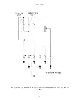
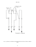
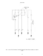
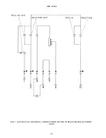
The internal connections of the relays are shown in Figs. 3, 4, 5, 6, and 7.
Содержание GEK-45404F
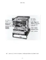
Страница 18: ...GEK 45404 18 FIG 1 8043181 0 TYPE IAV51D RELAY REMOVED FROM CASE FRONT VIEW ...
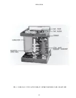
Страница 19: ...GEK 45404 19 FIG 2 8043182 0 TYPE IAV51D RELAY REMOVED FROM CASE REAR VIEW ...
Страница 20: ...GEK 45404 20 FIG 3 K 6400439 5 INTERNAL CONNECTIONS OF THE TYPE IAV51D RELAY FRONT VIEW ...
Страница 21: ...GEK 45404 21 FIG 4 362A514 3 INTERNAL CONNECTIONS OF THE TYPE IAV51K RELAY FRONT VIEW ...
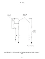
Страница 22: ...GEK 45404 22 FIG 5 K 6556505 0 INTERNAL CONNECTIONS OF THE TYPE IAV52C RELAY FRONT VIEW ...
Страница 23: ...GEK 45404 23 FIG 6 418A790 0 INTERNAL CONNECTIONS OF THE TYPE IAV52D RELAY FRONT VIEW ...
Страница 24: ...GEK 45404 24 FIG 7 0257A8379 0 INTERNAL CONNECTIONS OF THE TYPEIAV52K RELAY FRONT VIEW ...
Страница 27: ...GEK 45404 27 FIG 10 K6154391 3 TEST CONNECTIONS FOR OVERVOLTAGE RELAYS ...
Страница 29: ...GEK 45404 29 FIG 12 8025039 0 CROSS SECTION OF DRAWOUT CASE SHOWING POSITION OF AUXILIARY BRUSH ...
Страница 30: ...GEK 45404 30 FIG 13 0275A4399 0 OUTLINE OF IAV51K AND IAV52K EXTERNAL CAPACITOR ...
Страница 31: ...GEK 45404 31 FIG 14 K6209270 2 OUTLINE AND PANEL DRILLING FOR RELAY TYPES IAV51D 52D AND IAV52C ...
Страница 32: ...GEK 45404 32 FIG 15 K6209271 8 OUTLINE AND PANEL DRILLLING FOR RELAY TYPES IAV51K AND IAV52K ...