


GEK-45404
14
ADJUSTMENTS
Target and Seal-in Unit
For trip coils operating on current ranging from 0.2 up to 2.0 amperes at the minimum control
voltage, set the target and seal-in tap plug in the 0.2- ampere tap.
For trip coils operating on currents ranging from 2 to 30 amperes at the minimum control voltage,
place the tap plug in the 2.0-ampere tap.
The tap plug is the screw holding the right-hand stationary contact of the seal-in element. To change
the tap setting, first remove the connecting plug. Then, take a screw from the left-hand stationary
contact and place it in the desired tap. Next, remove the screw from the other tap, and place it in the
left-hand contact. This procedure is necessary to prevent the right- hand stationary contact from
getting out of adjustment. Screws should not be in both taps at the same time, as pickup for DC will
be the higher tap value and AC pickup will be increased.
Voltage Setting
The voltage at which the contacts operate may be changed by changing the tap of the IAV51D,
IAV52D, and IAV51K relays.
The pickup of any of the relays, when set for minimum pickup, can be adjusted by means of the
spring adjusting ring. The ring may be turned by inserting a tool in the notches around the edge. By
turning the ring, the operating voltage of the IAV52C relay may be brought into agreement with the
nameplate value, and in the same way the IAV51D, IAV51K, and IAV52K relays may be brought
into agreement with the minimum tap setting.
For taps other than minimum, the slide band on the adjustable resistor associated with the selected
tap, in series with the operating coil, should be moved until the pickup is at tap voltage. This
adjustment should not be made until the spring adjustment for minimum pickup is made, since the
spring adjustment sets the basic torque level of the relay.
Adjustments for pickup between calibrated taps can be made by selecting the tap closest to the
desired voltage and then adjusting the resistor band associated with the tap selected.
The relay is adjusted at the factory to operate from any time-dial position at a minimum voltage that
is 8% of rated voltage. The relays reset at 90% or more of the operating value. Operating voltage for
the IAV51D, IAV52D, IAV51K, and IAV52K relays is the minimum voltage for a given tap setting
at which the contacts just make.
Содержание GEK-45404F
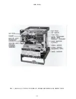
Страница 18: ...GEK 45404 18 FIG 1 8043181 0 TYPE IAV51D RELAY REMOVED FROM CASE FRONT VIEW ...
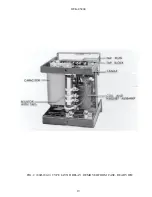
Страница 19: ...GEK 45404 19 FIG 2 8043182 0 TYPE IAV51D RELAY REMOVED FROM CASE REAR VIEW ...
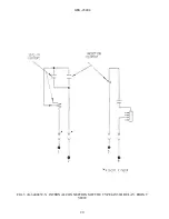
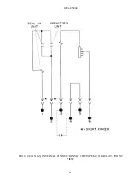
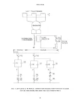
Страница 20: ...GEK 45404 20 FIG 3 K 6400439 5 INTERNAL CONNECTIONS OF THE TYPE IAV51D RELAY FRONT VIEW ...
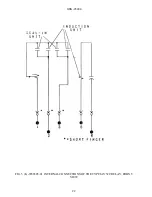
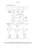
Страница 21: ...GEK 45404 21 FIG 4 362A514 3 INTERNAL CONNECTIONS OF THE TYPE IAV51K RELAY FRONT VIEW ...
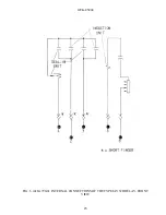
Страница 22: ...GEK 45404 22 FIG 5 K 6556505 0 INTERNAL CONNECTIONS OF THE TYPE IAV52C RELAY FRONT VIEW ...
Страница 23: ...GEK 45404 23 FIG 6 418A790 0 INTERNAL CONNECTIONS OF THE TYPE IAV52D RELAY FRONT VIEW ...
Страница 24: ...GEK 45404 24 FIG 7 0257A8379 0 INTERNAL CONNECTIONS OF THE TYPEIAV52K RELAY FRONT VIEW ...
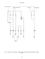
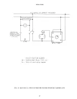
Страница 27: ...GEK 45404 27 FIG 10 K6154391 3 TEST CONNECTIONS FOR OVERVOLTAGE RELAYS ...
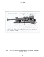
Страница 29: ...GEK 45404 29 FIG 12 8025039 0 CROSS SECTION OF DRAWOUT CASE SHOWING POSITION OF AUXILIARY BRUSH ...
Страница 30: ...GEK 45404 30 FIG 13 0275A4399 0 OUTLINE OF IAV51K AND IAV52K EXTERNAL CAPACITOR ...
Страница 31: ...GEK 45404 31 FIG 14 K6209270 2 OUTLINE AND PANEL DRILLING FOR RELAY TYPES IAV51D 52D AND IAV52C ...
Страница 32: ...GEK 45404 32 FIG 15 K6209271 8 OUTLINE AND PANEL DRILLLING FOR RELAY TYPES IAV51K AND IAV52K ...