GEK-45404
4
APPLICATION
These are single-phase, sensitive, time-delay overvoltage relays. They are principally applicable for
sensitive overvoltage ground detection for high-impedance grounded generators or for ungrounded
power systems. These relays all have a capacitor in series with the operating coil. For the IAV51K
and IAV52K relays, this capacitor is external to the relay because of its large size. The effect of the
capacitor is to tune the relay coil circuit so that the relay pickup on third harmonic (180Hz) voltage is
approximately eight times the relay pickup at 60 Hz. This is particularly important in overvoltage
ground detection for generators, since they produce a large third- harmonic component of voltage
during normal operation.
The external connection diagram for the IAV51K or the IAV52K relay for sensitive generator ground
detection is shown in Fig. 8. This is a typical protection scheme for a unit generator transformer
using a distribution transformer connected in the neutral with a resistor across the transformer
secondary. The IAV51K/52K relays are usually used for this application because they provide the
very sensitive 5.4 volt pickup rating. This enables the relay to detect a ground fault within a few
percent of the winding from the neutral. Since the power transformer and the station service
transformer in a unit generator transformer scheme are both connected in delta on the generator side,
coordination with other protection is virtually unnecessary and the ground relay used can be very
sensitive. Some time delay in relay operation is usually used to coordinate with fuses protecting
against faults on the secondary side of potential transformers that are normally connected to the
generator terminals. The usual practice is to use these relays to trip the generator breaker and shut
down the machine. If the relay is used only to sound an alarm when a ground fault is detected, the
application should be reviewed. It may be necessary to add another relay to provide ground
protection with good sensitivity simultaneously with a high continuous-voltage rating.
The resistor, shown in Fig. 8 connected across the broken delta secondary of the PT's, or alternatively
connected in series in the primary neutral connection, is usually required to prevent the occurrence of
ferro-resonance. This phenomenon could occur due to the interaction of the PT inductance with the
distributed capacitance-to-ground of the primary power system.
The external connection diagram for the IAV51D, 52D, or the IAV52C relay for ground-fault
detection on an ungrounded power system is shown in Fig. 9. The relay operates to detect the first
ground fault that occurs on the system, connections so that it can be removed before a second
ground occurs, causing a double phase-to-ground fault, which requires a service interruption. Since
the relay may be applied merely to sound an alarm in this application, it is necessary that it be
continuously rated for the full broken-delta voltage expected for a single phase-to-ground fault
located right at the potential transformers, or some automatic means must be employed to disconnect
the relay from the voltage supply.
When this fault occurs it is equivalent to shorting out one phase of the potential transformer primary.
The other two unfaulted phases of the PT primaries now have full phase-to-phase voltage applied
and their corresponding dJelta secondaries will be supplying
√
3 times their normal rated voltage.
The broken delta equivalent voltage will be these two voltages added in series at a 60
o
angle and the
Содержание GEK-45404F
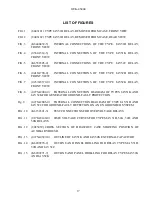
Страница 18: ...GEK 45404 18 FIG 1 8043181 0 TYPE IAV51D RELAY REMOVED FROM CASE FRONT VIEW ...
Страница 19: ...GEK 45404 19 FIG 2 8043182 0 TYPE IAV51D RELAY REMOVED FROM CASE REAR VIEW ...
Страница 20: ...GEK 45404 20 FIG 3 K 6400439 5 INTERNAL CONNECTIONS OF THE TYPE IAV51D RELAY FRONT VIEW ...
Страница 21: ...GEK 45404 21 FIG 4 362A514 3 INTERNAL CONNECTIONS OF THE TYPE IAV51K RELAY FRONT VIEW ...
Страница 22: ...GEK 45404 22 FIG 5 K 6556505 0 INTERNAL CONNECTIONS OF THE TYPE IAV52C RELAY FRONT VIEW ...
Страница 23: ...GEK 45404 23 FIG 6 418A790 0 INTERNAL CONNECTIONS OF THE TYPE IAV52D RELAY FRONT VIEW ...
Страница 24: ...GEK 45404 24 FIG 7 0257A8379 0 INTERNAL CONNECTIONS OF THE TYPEIAV52K RELAY FRONT VIEW ...
Страница 27: ...GEK 45404 27 FIG 10 K6154391 3 TEST CONNECTIONS FOR OVERVOLTAGE RELAYS ...
Страница 29: ...GEK 45404 29 FIG 12 8025039 0 CROSS SECTION OF DRAWOUT CASE SHOWING POSITION OF AUXILIARY BRUSH ...
Страница 30: ...GEK 45404 30 FIG 13 0275A4399 0 OUTLINE OF IAV51K AND IAV52K EXTERNAL CAPACITOR ...
Страница 31: ...GEK 45404 31 FIG 14 K6209270 2 OUTLINE AND PANEL DRILLING FOR RELAY TYPES IAV51D 52D AND IAV52C ...
Страница 32: ...GEK 45404 32 FIG 15 K6209271 8 OUTLINE AND PANEL DRILLLING FOR RELAY TYPES IAV51K AND IAV52K ...


