background image

GEK-45404

19

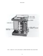
FIG. 2  (8043182-0)  TYPE IAV51D RELAY, REMOVED FROM CASE, REAR VIEW

Содержание GEK-45404F

Страница 1: ...F MULTILIN GE Power Management INSTRUCTIONS OVERVOLTAGE RELAYS TYPES IAV 51D K 52C D K GE Power Management 205 Great Valley Parkway Malvern PA 19355 USA Click here to get to our homepage http www gemultilin com ...

Страница 2: ...5 MAINTENANCE 15 DISK AND BEARINGS 15 CONTACT CLEANING 16 SERVICING 16 RENEWAL PARTS 16 LIST OF ILLUSTRATIONS 17 Cover Photo 8043180 These instructions do not purport to cover all details or variations in equipment nor provide for every possible contingency to be met in connection with installation operation or maintenance Should further information be desired or should particular problems arise w...

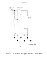
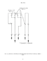
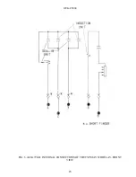
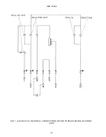
Страница 3: ...lings are shown in Figs 14 and 15 Fig 13 shows the outline for an external capacitor when used The internal connections of the relays are indicated in the table Each relay contains a target seal in unit that is used to protect the relay main contacts and control spring from damage due to breaker trip current TABLE A CONTINUOUS RATING VOLTS PICKUP RANGE VOLTS TAPS CONTACTS INTERNAL CONNECTIONS FIGU...

Страница 4: ...ers that are normally connected to the generator terminals The usual practice is to use these relays to trip the generator breaker and shut down the machine If the relay is used only to sound an alarm when a ground fault is detected the application should be reviewed It may be necessary to add another relay to provide ground protection with good sensitivity simultaneously with a high continuous vo...

Страница 5: ...he 2 ampere tap has a DC resistance of 0 13 ohms and a 60 cycle impedance of 0 53 ohms while the 0 2 ampere tap has a 7 ohm DC resistance and a 52 ohm 60 cycle impedance The tap setting used on the seal in element is determined by the current drawn by the trip coil The 0 2 ampere tap is for use with trip coils that operate on currents ranging from 0 2 up to 2 0 amperes at the minimum control volta...

Страница 6: ...0 12 3 0 93 11 4 IAV51D 199 A 16 32 0 0 31 9 9 IAV52D B 24 27 9 0 56 15 6 C 40 20 0 0 81 16 2 D 64 13 2 0 92 12 2 IAV51D 345 A 28 41 5 0 37 15 5 B 42 35 0 0 62 21 6 C 70 23 9 0 85 20 3 D 112 13 6 0 95 12 9 IAV51K 67 A 5 4 34 0 0 31 10 5 IAV52K B 7 5 31 0 0 52 15 9 C 12 5 23 1 0 77 17 7 D 20 16 0 0 9 14 4 115 No Taps 24 2 0 21 5 0 IAV52C 199 No Taps 32 0 0 31 9 9 345 No Taps 41 5 0 37 15 5 1AV51D 1...

Страница 7: ... pickup volts TABLE IIIB 60 Cycle Burden at Rated Voltages RELAY TYPES VOLTAGE RATINGS TAP SETTINGS VOLT AMPS POWER FACTOR WATTS 1AV51D 115 A 10 0 46 0 99 0 46 B 15 0 62 1 0 0 62 C 25 0 96 1 0 0 96 D 40 1 48 1 0 1 48 IAV51D 199 A 16 0 41 0 94 0 38 IAV52D B 24 0 56 0 98 0 55 C 40 0 89 0 99 0 88 D 64 1 38 1 0 1 37 IAV51D 345 A 28 0 48 0 86 0 41 B 42 0 66 0 95 0 62 C 70 1 02 0 98 1 01 D 112 1 4 0 99 ...

Страница 8: ...acts is determined by the setting of the time dial at the top of the shaft The IAV51D has a capacitor and tapped resistor connected in series with the operating coil The capacitor is added to tune the circuit giving a low pickup voltage at rated frequency At rated voltage the operating U magnet is highly saturated increasing the impedance of the circuit thus limiting the current to a safe value Th...

Страница 9: ...provided for either mounting The cover attaches to the case and also carries the reset mechanism when one is required Two of the cover screws have provision for a sealing wire The case has studs or screw connections at the bottom for the external connections The electrical connections between the relay units and the case studs are made through spring backed contact fingers mounted in stationary mo...

Страница 10: ...sturbed STORAGE If the relays are not to be installed immediately they should be stored in their original cartons in a place that is free from moisture dust and metallic chips Foreign matter collected on the outside of the case may find its way inside when the cover is removed and cause trouble in the operation of the relay ACCEPTANCE TESTS Immediately upon receipt of the relay an inspection and a...

Страница 11: ...g should deflect about 1 64 inch and the stop arm should clear the molded block by at least 0 020 inch Any foreign material must be cleaned out of stator air gaps Clearance between the disk and either the drag magnet or U magnet should be at least 0 010 inch for any position of the disk End play of the disk should be from 0 005 inch to 0 010 inch End play should not be so great as to allow the dis...

Страница 12: ...e in order to test alternating current relays properly it is essential to use a sine wave of current and or voltage The purity of the sine wave i e its freedom from harmonics cannot be expressed as a finite number for any particular relay however and relay using tuned circuits RL or RC networks or saturating electromagnets such as time overcurrent relays would be especially affected by non sinusoi...

Страница 13: ...shows outline and panel drilling for relay Types IAV51K and IAV52K CONNECTIONS Internal connections are shown in Figs 3 to 7 for the various relays GROUND CONNECTIONS One of the mounting studs or screws should be permanently grounded by a conductor not less than No 12 B S gage copper wire or its equivalent OPERATION Before the relay is put in service the pickup voltage and time voltage tests descr...

Страница 14: ...f the relays when set for minimum pickup can be adjusted by means of the spring adjusting ring The ring may be turned by inserting a tool in the notches around the edge By turning the ring the operating voltage of the IAV52C relay may be brought into agreement with the nameplate value and in the same way the IAV51D IAV51K and IAV52K relays may be brought into agreement with the minimum tap setting...

Страница 15: ...f tap setting The time obtained should be the value on the curve 15 PERIODIC CHECKS AND ROUTINE MAINTENANCE In view of the vital role of protective relays in the operation of a power system it is important that a periodic test program be followed It is recognized that the interval between periodic checks will vary depending upon environment type of relay and the user s experience with periodic tes...

Страница 16: ...insulating abrasive material in the contacts and thus prevent closing The burnishing tool described above can be obtained from the factory SERVICING For servicing and adjustments see applicable instructions under ACCEPTANCE TESTS INSTALLATION AND MAINTENANCE RENEWAL PARTS It is recommended that sufficient quantities of renewal parts be carried in stock to enable the prompt replacement of any that ...

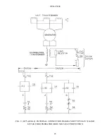
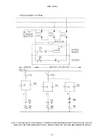
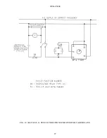
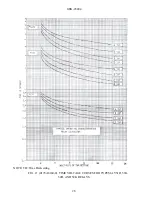
Страница 17: ...52K RELAY FRONT VIEW FIG 8 0275A2004 0 EXTERNAL CONNECTION DIAGRAM OF TYPES IAV51K AND IAV52K FOR GENERATOR GROUND FAULT PROTECTION Fig 9 0275A2003 0 EXTERNAL CONNECTION DIAGRAM OF TYPE IAV51D AND IAV52C FOR GROUND FAULT DETECTION ON AN UNGROUNDED SYSTEM FIG 10 K6154391 3 TEST CONNECTIONS FOR OVERVOLTAGE RELAYS FIG 11 0178A8140 0 TIME VOLTAGE CURVES FOR TYPES IAV51D 51K 52D AND 52K RELAYS FIG 12 8...

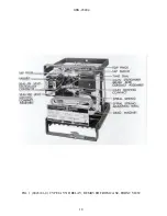
Страница 18: ...GEK 45404 18 FIG 1 8043181 0 TYPE IAV51D RELAY REMOVED FROM CASE FRONT VIEW ...

Страница 19: ...GEK 45404 19 FIG 2 8043182 0 TYPE IAV51D RELAY REMOVED FROM CASE REAR VIEW ...

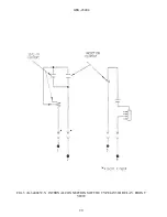
Страница 20: ...GEK 45404 20 FIG 3 K 6400439 5 INTERNAL CONNECTIONS OF THE TYPE IAV51D RELAY FRONT VIEW ...

Страница 21: ...GEK 45404 21 FIG 4 362A514 3 INTERNAL CONNECTIONS OF THE TYPE IAV51K RELAY FRONT VIEW ...

Страница 22: ...GEK 45404 22 FIG 5 K 6556505 0 INTERNAL CONNECTIONS OF THE TYPE IAV52C RELAY FRONT VIEW ...

Страница 23: ...GEK 45404 23 FIG 6 418A790 0 INTERNAL CONNECTIONS OF THE TYPE IAV52D RELAY FRONT VIEW ...

Страница 24: ...GEK 45404 24 FIG 7 0257A8379 0 INTERNAL CONNECTIONS OF THE TYPEIAV52K RELAY FRONT VIEW ...

Страница 25: ...GEK 45404 25 FIG 8 0275A2004 0 EXTERNAL CONNECTION DIAGRAM OF TYPES IAV51KAND IAV52K FOR GENERATOR GROUND FAULT PROTECTION ...

Страница 26: ...GEK 45404 26 FIG 9 0275A2003 0 EXTERNAL CONNECTION DIAGRAM OF TYPE IAV51D IAV52C AND IAV52D FOR GROUND FAULT DETECTION ON AN UNGROUNDED SYSTEM ...

Страница 27: ...GEK 45404 27 FIG 10 K6154391 3 TEST CONNECTIONS FOR OVERVOLTAGE RELAYS ...

Страница 28: ...GEK 45404 28 NOTE TD Time Dial setting FIG 11 0178A8140 0 TIME VOLTAGE CURVES FOR TYPES IAV51D 51K 52D AND 52K RELAYS ...

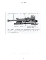
Страница 29: ...GEK 45404 29 FIG 12 8025039 0 CROSS SECTION OF DRAWOUT CASE SHOWING POSITION OF AUXILIARY BRUSH ...

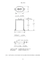
Страница 30: ...GEK 45404 30 FIG 13 0275A4399 0 OUTLINE OF IAV51K AND IAV52K EXTERNAL CAPACITOR ...

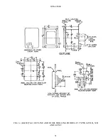
Страница 31: ...GEK 45404 31 FIG 14 K6209270 2 OUTLINE AND PANEL DRILLING FOR RELAY TYPES IAV51D 52D AND IAV52C ...

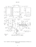
Страница 32: ...GEK 45404 32 FIG 15 K6209271 8 OUTLINE AND PANEL DRILLLING FOR RELAY TYPES IAV51K AND IAV52K ...

Отзывы: