GEK-45404
11
CAUTION:
Every circuit in the drawout case has an auxiliary brush. It is especially important on current
circuits and other circuits with shorting bars that the auxiliary brush be bent high enough to
engage the connecting plug or test plug before the main brushes do. This will prevent Current
Transformer (CT) secondary circuits from being opened.
MECHANICAL INSPECTION
On relays that have time dials, the dials will be set at zero before the relay leaves the factory. It is
necessary to change this setting to open the relay contacts.
On all relays with locked time dials, make sure the two time-dial locking screws are tight. These
locking screws are to prevent the dial from moving when the relay is subjected to high operating
torque.
The moving contact should be fastened securely in its support, and should engage the stationary
contact about in the middle, or at least 1/16 inch inside the periphery of the stationary contact.
The stop-arm leaf spring should deflect about 1/64 inch and the stop arm should clear the molded
block by at least 0.020 inch.
Any foreign material must be cleaned out of stator air gaps. Clearance between the disk and either
the drag magnet or U magnet should be at least 0.010 inch for any position of the disk.
End play of the disk should be from 0.005 inch to 0.010 inch. End play should not be so great as to
allow the disk to strike the U magnet or the drag magnet. Check that top and bottom pivot and
bearing screws are tight.
There should be no noticeable friction in the rotating structure.
Rotate the time dial to the zero position. Check by means of a neon lamp that the contacts just close;
there should be approximately 1/32 inch wipe on the stationary contact. If the contact does not close,
adjust the disk position by backing off the two clamping screws on the stop arm and rotating the stop
arm relative to the cutout in the disk. This is a coarse adjustment. Retighten the clamping screws.
For fine adjustment of contact closing, run the stationary contact brush in or out by means of its
adjusting screw; after this adjustment, check that the screw is held firmly in its support.
Содержание GEK-45404F
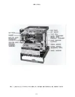
Страница 18: ...GEK 45404 18 FIG 1 8043181 0 TYPE IAV51D RELAY REMOVED FROM CASE FRONT VIEW ...
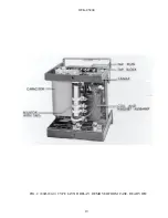
Страница 19: ...GEK 45404 19 FIG 2 8043182 0 TYPE IAV51D RELAY REMOVED FROM CASE REAR VIEW ...
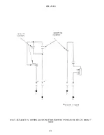
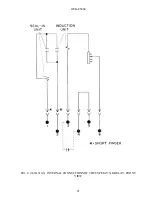
Страница 20: ...GEK 45404 20 FIG 3 K 6400439 5 INTERNAL CONNECTIONS OF THE TYPE IAV51D RELAY FRONT VIEW ...
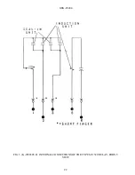
Страница 21: ...GEK 45404 21 FIG 4 362A514 3 INTERNAL CONNECTIONS OF THE TYPE IAV51K RELAY FRONT VIEW ...
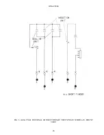
Страница 22: ...GEK 45404 22 FIG 5 K 6556505 0 INTERNAL CONNECTIONS OF THE TYPE IAV52C RELAY FRONT VIEW ...
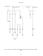
Страница 23: ...GEK 45404 23 FIG 6 418A790 0 INTERNAL CONNECTIONS OF THE TYPE IAV52D RELAY FRONT VIEW ...
Страница 24: ...GEK 45404 24 FIG 7 0257A8379 0 INTERNAL CONNECTIONS OF THE TYPEIAV52K RELAY FRONT VIEW ...
Страница 27: ...GEK 45404 27 FIG 10 K6154391 3 TEST CONNECTIONS FOR OVERVOLTAGE RELAYS ...
Страница 29: ...GEK 45404 29 FIG 12 8025039 0 CROSS SECTION OF DRAWOUT CASE SHOWING POSITION OF AUXILIARY BRUSH ...
Страница 30: ...GEK 45404 30 FIG 13 0275A4399 0 OUTLINE OF IAV51K AND IAV52K EXTERNAL CAPACITOR ...
Страница 31: ...GEK 45404 31 FIG 14 K6209270 2 OUTLINE AND PANEL DRILLING FOR RELAY TYPES IAV51D 52D AND IAV52C ...
Страница 32: ...GEK 45404 32 FIG 15 K6209271 8 OUTLINE AND PANEL DRILLLING FOR RELAY TYPES IAV51K AND IAV52K ...


