GEK-45404
8
50 - Cycle Burden at Rated Voltages
RELAY
TYPES
VOLTAGE
RATINGS
TAP**SETTINGS
VOLT-AMPS
POWER
FACTOR
WATTS
1AV51D
115
A(10)
0.52
0.98
0.52
B(15)
0.67
0.99
0.67
C(25)
1.0
1.0
1.0
D(40)
1.52
1.0
1.52
IAV51D
199
A(16)
0.32
0.85
0.27
B(24)
0.5
0.93
0.46
C(40)
0.83
0.97
0.81
D(64)
1.33
0.99
1.32
IAV51D
345
A(28)
0.39
0.96
0.37
B(42)
0.58
0.98
0.57
C(70)
0.96
0.99
0.95
D(112)
1.35
1.0
1.35
IAV51K
67
A(5.4)
0.38
0.91
0.34
IAV52K
B(7.5)
0.52
0.95
0.5
C(12.5)
0.87
0.98
0.85
D(20)
1.42
0.99
1.41
115
No Taps
0.27
0.98
0.27
IAV52C
199
No Taps
0.32
0.85
0.27
345
No Taps
0.39
0.96
0.37
**Minimum pickup volts
OPERATING CHARACTERISTICS
The Type IAV51D relay is a low-pickup voltage relay normally used for ground fault protection on
AC rotating machines. It has single-circuit closing contacts that close when the voltage increases to
pickup value, as set on the tap block. The time delay in closing the contacts is determined by the
setting of the time dial at the top of the shaft. The IAV51D has a capacitor and tapped resistor
connected in series with the operating coil. The capacitor is added to tune the circuit, giving a low
pickup voltage at rated frequency. At rated voltage the operating U magnet is highly saturated,
increasing the impedance of the circuit, thus limiting the current to a safe value. The taps on the
resistor are connected to the tap block to provide a four-to-one range of pickup. As shown in the
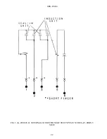
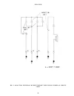
typical external connection diagram, Fig. 8, this relay is connected to the machine neutral potential
transformer through a closed contact on the auxiliary tripping relay, hence is energized only when a
ground occurs. To obtain still-lower pickup than the normal calibration, it is permissible to insert an
inverted potential transformer between the machine neutral transformer and the relay coil circuit.
The IAV51D has a seal-in element. Time curves are shown in Fig. 11.
The IAV51K relay is similar to the IAV51D except that it has an external capacitor. Time curves are
shown in Fig. 11.
Содержание GEK-45404F
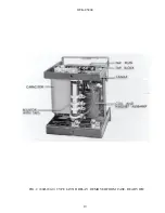
Страница 18: ...GEK 45404 18 FIG 1 8043181 0 TYPE IAV51D RELAY REMOVED FROM CASE FRONT VIEW ...
Страница 19: ...GEK 45404 19 FIG 2 8043182 0 TYPE IAV51D RELAY REMOVED FROM CASE REAR VIEW ...
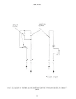
Страница 20: ...GEK 45404 20 FIG 3 K 6400439 5 INTERNAL CONNECTIONS OF THE TYPE IAV51D RELAY FRONT VIEW ...
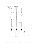
Страница 21: ...GEK 45404 21 FIG 4 362A514 3 INTERNAL CONNECTIONS OF THE TYPE IAV51K RELAY FRONT VIEW ...
Страница 22: ...GEK 45404 22 FIG 5 K 6556505 0 INTERNAL CONNECTIONS OF THE TYPE IAV52C RELAY FRONT VIEW ...
Страница 23: ...GEK 45404 23 FIG 6 418A790 0 INTERNAL CONNECTIONS OF THE TYPE IAV52D RELAY FRONT VIEW ...
Страница 24: ...GEK 45404 24 FIG 7 0257A8379 0 INTERNAL CONNECTIONS OF THE TYPEIAV52K RELAY FRONT VIEW ...
Страница 27: ...GEK 45404 27 FIG 10 K6154391 3 TEST CONNECTIONS FOR OVERVOLTAGE RELAYS ...
Страница 29: ...GEK 45404 29 FIG 12 8025039 0 CROSS SECTION OF DRAWOUT CASE SHOWING POSITION OF AUXILIARY BRUSH ...
Страница 30: ...GEK 45404 30 FIG 13 0275A4399 0 OUTLINE OF IAV51K AND IAV52K EXTERNAL CAPACITOR ...
Страница 31: ...GEK 45404 31 FIG 14 K6209270 2 OUTLINE AND PANEL DRILLING FOR RELAY TYPES IAV51D 52D AND IAV52C ...
Страница 32: ...GEK 45404 32 FIG 15 K6209271 8 OUTLINE AND PANEL DRILLLING FOR RELAY TYPES IAV51K AND IAV52K ...


