


GEK-45404
12
ELECTRICAL TESTS
Drawout Relays - General
Since all drawout relays in service operate in their cases, it is recommended that they be tested in
their cases or an equivalent steel case. In this way any magnetic effects of the enclosure will be
accurately duplicated during testing. A relay may be tested without removing it from the panel by
using a 12XLA13A test plug. This plug makes connections only with the relay and does not disturb
any shorting bars in the case. Of course, the 12XLA12A test plug may also be used. Although this
test plug allows greater testing flexibility, it also requires CT shorting jumpers and the exercise of
greater care since connections are made to both the relay and the external circuitry.
Power Requirements - General
All alternating-current-operated devices are affected by frequency. Since non-sinusoidal waveforms
can be analyzed as a fundamental frequency plus harmonics of the fundamental frequency, it follows
that alternating-current devices (relays) will be affected by the applied waveform.
Therefore, in order to test alternating-current relays properly it is essential to use a sine wave of
current and/or voltage. The purity of the sine wave (i.e. its freedom from harmonics) cannot be
expressed as a finite number for any particular relay; however, and relay using tuned circuits, RL or
RC networks, or saturating electromagnets (such as time-overcurrent relays) would be especially
affected by non-sinusoidal waveforms.
Similarly, relays requiring DC control power should be tested using direct current and not full-wave
rectified power. Unless the rectified supply is well filtered, many relays will not operate properly
due to the dips in the rectified power. Zener diodes, for example, can turn off during these dips. As a
general rule the DC source should not contain more than 5% ripple.
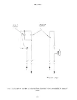
Pickup-voltage Test
The pickup voltage should be checked; for the IAV51D, IAV51K, and IAV52K, the pickup voltage
should be checked on more than one tap. See relay nameplate for value of pickup voltage (closing
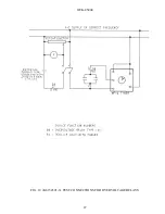
volts). Test connections, Fig. 10, are the same as for the time-voltage test except that the timer is not
required.
Time-voltage Test
The time-voltage curves should be checked for one or more settings. Recommended test connections
for this test are shown in Fig. 10.
Содержание GEK-45404F
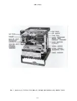
Страница 18: ...GEK 45404 18 FIG 1 8043181 0 TYPE IAV51D RELAY REMOVED FROM CASE FRONT VIEW ...
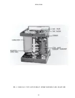
Страница 19: ...GEK 45404 19 FIG 2 8043182 0 TYPE IAV51D RELAY REMOVED FROM CASE REAR VIEW ...
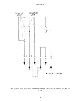
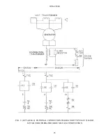
Страница 20: ...GEK 45404 20 FIG 3 K 6400439 5 INTERNAL CONNECTIONS OF THE TYPE IAV51D RELAY FRONT VIEW ...
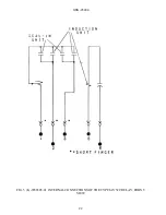
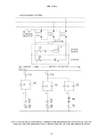
Страница 21: ...GEK 45404 21 FIG 4 362A514 3 INTERNAL CONNECTIONS OF THE TYPE IAV51K RELAY FRONT VIEW ...
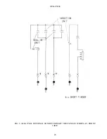
Страница 22: ...GEK 45404 22 FIG 5 K 6556505 0 INTERNAL CONNECTIONS OF THE TYPE IAV52C RELAY FRONT VIEW ...
Страница 23: ...GEK 45404 23 FIG 6 418A790 0 INTERNAL CONNECTIONS OF THE TYPE IAV52D RELAY FRONT VIEW ...
Страница 24: ...GEK 45404 24 FIG 7 0257A8379 0 INTERNAL CONNECTIONS OF THE TYPEIAV52K RELAY FRONT VIEW ...
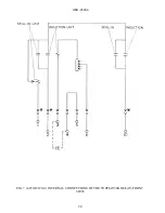
Страница 27: ...GEK 45404 27 FIG 10 K6154391 3 TEST CONNECTIONS FOR OVERVOLTAGE RELAYS ...
Страница 29: ...GEK 45404 29 FIG 12 8025039 0 CROSS SECTION OF DRAWOUT CASE SHOWING POSITION OF AUXILIARY BRUSH ...
Страница 30: ...GEK 45404 30 FIG 13 0275A4399 0 OUTLINE OF IAV51K AND IAV52K EXTERNAL CAPACITOR ...
Страница 31: ...GEK 45404 31 FIG 14 K6209270 2 OUTLINE AND PANEL DRILLING FOR RELAY TYPES IAV51D 52D AND IAV52C ...
Страница 32: ...GEK 45404 32 FIG 15 K6209271 8 OUTLINE AND PANEL DRILLLING FOR RELAY TYPES IAV51K AND IAV52K ...