GEK-45404
15
Time Setting
The time of operation of the overvoltage relay is determined primarily by the setting of the time dial.
Further adjustment is obtained by moving the permanent magnet along its supporting shelf; moving
the magnet in toward the back of the relay decreases the time, while moving it out increases the time.
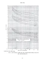
Fig. 11 shows the time-voltage characteristics of the IAV51D, IAV52D, IAV51K and IAV52K for
the four tap settings for the Number 1, 5, and 10 time- dial positions. The time-voltage characteristic
of the 1AV52C, which has no taps, is the same as for the "A" tap in the D & K relays.
To make time settings, set the time dial to the number required (to give the desired characteristic) by
turning it until the number lines up with the notch in the adjacent frame. The time indicated by the
curves is the time required to close the relay contacts when the voltage is suddenly increased from a
value below pickup to the value on the curve (expressed in multiples of tap setting). The time
obtained should be the value on the curve ± 15%.
PERIODIC CHECKS AND ROUTINE MAINTENANCE
In view of the vital role of protective relays in the operation of a power system, it is important that a
periodic test program be followed. It is recognized that the interval between periodic checks will
vary depending upon environment, type of relay and the user's experience with periodic testing. Until
the user has accumulated enough experience to select the test interval best suited to his individual
requirements, it is suggested that the points listed under INSTALLATION PROCEDURE be
checked every six months.
* Revised since last issue
MAINTENANCE
These relays are adjusted at the factory and it is advisable not to disturb the adjustments. If for any
reason, they have been disturbed, the following points should be observed in restoring them.
DISK AND BEARINGS
The lower jewel may be tested for cracks by exploring its surface with the point of a fine needle. If it
is necessary to replace the jewel, the new jewel should be turned up until the disk is centered in the
air gap, after which it should be locked in position by the set screw provided for the purpose.
Содержание GEK-45404F
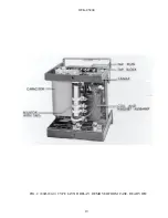
Страница 18: ...GEK 45404 18 FIG 1 8043181 0 TYPE IAV51D RELAY REMOVED FROM CASE FRONT VIEW ...
Страница 19: ...GEK 45404 19 FIG 2 8043182 0 TYPE IAV51D RELAY REMOVED FROM CASE REAR VIEW ...
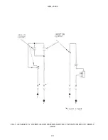
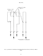
Страница 20: ...GEK 45404 20 FIG 3 K 6400439 5 INTERNAL CONNECTIONS OF THE TYPE IAV51D RELAY FRONT VIEW ...
Страница 21: ...GEK 45404 21 FIG 4 362A514 3 INTERNAL CONNECTIONS OF THE TYPE IAV51K RELAY FRONT VIEW ...
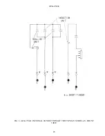
Страница 22: ...GEK 45404 22 FIG 5 K 6556505 0 INTERNAL CONNECTIONS OF THE TYPE IAV52C RELAY FRONT VIEW ...
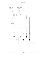
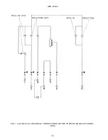
Страница 23: ...GEK 45404 23 FIG 6 418A790 0 INTERNAL CONNECTIONS OF THE TYPE IAV52D RELAY FRONT VIEW ...
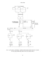
Страница 24: ...GEK 45404 24 FIG 7 0257A8379 0 INTERNAL CONNECTIONS OF THE TYPEIAV52K RELAY FRONT VIEW ...
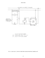
Страница 27: ...GEK 45404 27 FIG 10 K6154391 3 TEST CONNECTIONS FOR OVERVOLTAGE RELAYS ...
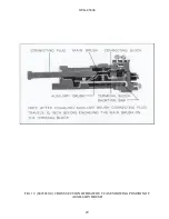
Страница 29: ...GEK 45404 29 FIG 12 8025039 0 CROSS SECTION OF DRAWOUT CASE SHOWING POSITION OF AUXILIARY BRUSH ...
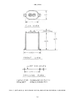
Страница 30: ...GEK 45404 30 FIG 13 0275A4399 0 OUTLINE OF IAV51K AND IAV52K EXTERNAL CAPACITOR ...
Страница 31: ...GEK 45404 31 FIG 14 K6209270 2 OUTLINE AND PANEL DRILLING FOR RELAY TYPES IAV51D 52D AND IAV52C ...
Страница 32: ...GEK 45404 32 FIG 15 K6209271 8 OUTLINE AND PANEL DRILLLING FOR RELAY TYPES IAV51K AND IAV52K ...


