


TROUBLESHOOTING: Service Tips
Revision B
Dash 3000/4000 Patient Monitor
5-25
2000966-105
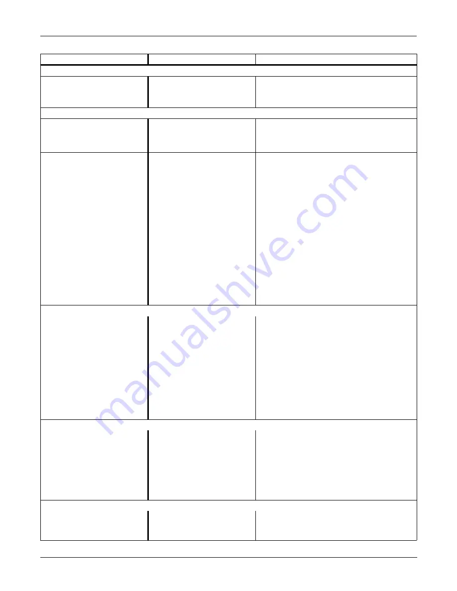
Optional Alarm Light Indicator
The red or yellow lights
do not light on boot up
of the monitor.
■
Cable may be loose or
disconnected.
■
Restore the connection.
■
LEDs are burned out.
■
Replace the alarm light assembly or PCB.
Defib Sync Problems
“Buzz” signal comes out
for ECG or BP.
■
BP is not zeroed.
■
Zero out the BP.
■
BP is not available.
■
Plug in a BP cable.
■
ECG leads fail.
■
Check patient connections.
Video Display Problems
There are bars/strips of
pixels missing on the
display in rows/columns.
Or only one row/column
of pixels on the display
is missing or never
turned on. The
remaining portion of the
display functions
properly.
■
Possible burned-out
pixels.
■
Run the display tests in the boot loader.
■
Replace the display assembly.
No display
■
Display may be in
standby mode.
■
Backlight inverted may
be defective.
■
Press the POWER button. If display still
does not appear within 10 seconds,
replace the display assembly.
■
Replace back light inverter.
Network Connector Problems
No network connection
when a network cable is
connected to the
monitor’s Network
Connector
■
The Dash monitor is
connected to a Dash Port
docking station. The
monitor’s Network
Connector is inactive
when it is connected to
the docking station.
■
Connect the network cable to the docking
station’s Ethernet connector.
■
The Dash monitor does
not have the optional
Unity Network option
enabled.
■
Purchase and enable the Unity Network
option.
Remote Control
The remote control does
not activate the display.
■
Cable or Autoport to
Mport adapter
connections may be loose.
■
Restore the connection.
■
Remote control needs to
be reset.
■
Disconnect and securely reconnect the
remote control from the monitor.
■
Remote control is
defective.
■
Replace the remote control with a known
good one.
Masimo SET SPO2
Probe or module
malfunction
■
Five or more consecutive
hardware failures have
occurred.
■
Review the input error log for Masimo
failure codes.
Problem
Reason
Solution
Содержание Dash 3000
Страница 11: ...Revision B Dash 3000 4000 Patient Monitor 1 1 2000966 105 1 INTRODUCTION ...
Страница 12: ...INTRODUCTION 1 2 Dash 3000 4000 Patient Monitor Revision B 2000966 105 For your notes ...
Страница 19: ...Revision B Dash 3000 4000 Patient Monitor 2 1 2000966 105 2 EQUIPMENT OVERVIEW ...
Страница 20: ...EQUIPMENT OVERVIEW 2 2 Dash 3000 4000 Patient Monitor Revision B 2000966 105 For your notes ...
Страница 43: ...Revision B Dash 3000 4000 Patient Monitor 3 1 2000966 105 3 INSTALLATION ...
Страница 44: ...INSTALLATION 3 2 Dash 3000 4000 Patient Monitor Revision B 2000966 105 For your notes ...
Страница 51: ...Revision B Dash 3000 4000 Patient Monitor 4 1 2000966 105 4 MAINTENANCE ...
Страница 52: ...MAINTENANCE 4 2 Dash 3000 4000 Patient Monitor Revision B 2000966 105 For your notes ...
Страница 93: ...Revision B Dash 3000 4000 Patient Monitor 5 1 2000966 105 5 TROUBLESHOOTING ...
Страница 94: ...TROUBLESHOOTING 5 2 Dash 3000 4000 Patient Monitor Revision B 2000966 105 For your notes ...
Страница 122: ...TROUBLESHOOTING Language Specific Information 5 30 Dash 3000 4000 Patient Monitor Revision B 2000966 105 For your notes ...
Страница 123: ...Revision B Dash 3000 4000 Patient Monitor 6 1 2000966 105 6 CONFIGURATION ...
Страница 124: ...CONFIGURATION 6 2 Dash 3000 4000 Patient Monitor Revision B 2000966 105 For your notes ...
Страница 144: ...CONFIGURATION 6 22 Dash 3000 4000 Patient Monitor Revision B 2000966 105 For your notes ...
Страница 145: ...Revision B Dash 3000 4000 Patient Monitor 7 1 2000966 105 7 CALIBRATION ...
Страница 146: ...CALIBRATION 7 2 Dash 3000 4000 Patient Monitor Revision B 2000966 105 For your notes ...
Страница 154: ...FIELD REPLACEABLE UNITS AND UPGRADES 8 2 Dash 3000 4000 Patient Monitor Revision B 2000966 105 For your notes ...
Страница 189: ...Revision B Dash 3000 4000 Patient Monitor 9 1 2000966 105 9 ASSEMBLY DRAWINGS ...
Страница 190: ...ASSEMBLY DRAWINGS 9 2 Dash 3000 4000 Patient Monitor Revision B 2000966 105 For your notes ...
Страница 201: ...ASSEMBLY DRAWINGS Theory Of Operation Revision B Dash 3000 4000 Patient Monitor 9 13 2000966 105 Block Diagram ...
Страница 230: ...ASSEMBLY DRAWINGS Port Connections 9 42 Dash 3000 4000 Patient Monitor Revision B 2000966 105 For your notes ...
Страница 231: ......
Страница 232: ...GE Medical Systems Information Technologies g gemedicalsystem com ...


