background image

DU-WS-0012-01 Rev B 5/24/16 GCX Corp. Page 10 of 15 


Service Loop 1 


Determine Cable Service Loop and Route Cables with Cable Sleeves 

Identify all cables that need to route through the Arm to the Channel 
and ensure they are long enough. Connect all cables to the device and 
organize cables so cables on the left side of the device route to the left 
side anchor points and cables from the right side of the device route to 
the anchor points on right side of the arm. Two Cable Sleeves are 
included 

– they are 30.5” (77.5cm) in length and determine the correct 

service loop for the cables from the front cable anchor point to the rear 
cable anchor point (Service Loop 2).  
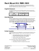
Insert cables into Cable Sleeves (see diagram below). Determine the 
service loop needed for the cables from their connections on the device 
to the front anchor points (Service Loop 1) 

– do this by tilting the device 

all the way forward and being sure there is adequate length to avoid 
damage to a connector or unintended disconnection of a cable.


Insert


cables into sleeve


Cable Sleeve must have a 1/4 rotation overlap minimum.


CAUTION: 

Cable sleeve material other than that supplied with the arm (or equivalent) should not be used 

without verification of function by GCX. 


Once Service Loop 1 to the front anchor points is determined, adjust the 
Cable Sleeve and secure cable bundle to Cable Anchor with cable tie 
1/2” (13mm) from the end of the Cable Sleeve. Before securing the 
cable tie, ensure the service loop to the device is still correct, then 
secure cables by pulling on the cable tie until the cable bundle does not 
move. Position the female receptacle of cable tie against the Arm before 
tightening. Use of pliers may assist in providing enough cable tie tension 
on the cable bundle. Clip excess length of the cable tie as flush as 
possible to avoid creation of a sharp edge.


1/2” (13mm) 

Clip excess length of the cable tie as flush as 
possible to avoid creation of a sharp edge.


Anchor Point


Service Loop 2


Service Loop 1 
(device dependent)


Содержание VHM-P

Страница 1: ...des mounting hardware and instructions OSHPD Pre Approval WC 0002 03 05 07 09 11 and 15 Dual Cable Hooks with 3 7 6 cm Down Post for Cable Management WMM 0006 13 www gcx com GCX is an ISO 13485 regist...

Страница 2: ...range 16 40 6 cm total travel Lateral range 90 degrees Load range 15 to 30 lb 6 8 to 13 6 kg or 25 to 45 lb 11 3 to 20 4 kg Maximum weight for flat panel 30 lb 13 6 kg Available with 8 or 14 Extensio...

Страница 3: ...11 0 Routine Maintenance 14 12 0 Cleaning the Arm 14 13 0 Troubleshooting the VHM P and VHM PL 15 Installation Time Approximately 10 15 minutes The purpose of this manual is to describe general instal...

Страница 4: ...es 2 3 4 6 9 7 VHM PL locking 1b 5 8 VHM P non locking 1a 1 0 Parts Reference The following parts and hardware are included and labeled accordingly Item Description Quantity 1 VHM P a or VHM PL b Chan...

Страница 5: ...ies Arms Do not remove device when arm is in a lowered position Refer to Installation Guide for additional information Remove the Device only when the Arm is at the highest position Safety Label Locat...

Страница 6: ...result in damage to equipment or injury If you are unable to adjust the arm or require service contact GCX technical support at 800 228 2555 or 1 707 773 1100 The mounted device or arm may move sudden...

Страница 7: ...ecure position Before mounting the Arm verify that the channel has been installed and approved in accordance with the channel installation guide included with the channel 5 4 Set Screws 2 upper Set Sc...

Страница 8: ...d slide device laterally into the Mounting Plate until the Plunger snaps into the clearance hole at the front of the Mounting Adapter Nylon Locking Screws After the device is installed tighten the 4 N...

Страница 9: ...al position Using a 5 32 hex wrench tighten or loosen the Counterbalance Adjustment Screw Counterbalance is correctly adjusted when the mounted device can be moved up or down with minimal force and do...

Страница 10: ...et wrench until desired tension is achieved Total adjustment is approximately to turn Caution Do not remove the Swivel Tension Nut 7 3 Swivel Tension Adjustment Swivel Tension Nut Tilt Tension Adjustm...

Страница 11: ...arts included for cable routing Cable Sleeves 2 Length 30 5 77 5cm Cable Ties 8 Cable Cover Cable Sleeve Four 4 Cable Anchors are provided at the front and four 4 at rear of the arm to secure cables a...

Страница 12: ...being sure there is adequate length to avoid damage to a connector or unintended disconnection of a cable Insert cables into sleeve Cable Sleeve must have a 1 4 rotation overlap minimum CAUTION Cable...

Страница 13: ...d below the Arm Figure B Pivot the Cable Cover up towards the Arm Figure C Gently squeeze the front of the Cable Cover and insert tabs of the Cable Cover into the mating slots to secure the Cable Cove...

Страница 14: ...Loop 2 from the front Cable Anchor point to the rear Cable Anchor point after securing the cables to the front Cable Anchor points and already determining Service Loop 1 from device to front anchor po...

Страница 15: ...el Thread and secure the captive screw into the mounting hole under the pivot assembly with a 2 Phillips screw driver Do not overtighten the screw 9 1 Installing the upper Rear Pivot Cover Place the P...

Страница 16: ...quipment refer to the specific instructions delivered with those products 12 0 Cleaning the VHM P and VHM PL Arm 11 0 Routine Maintenance Routine Maintenance Check List Section Counterbalance With the...

Страница 17: ...m with compatible Load Rating section 3 0 Mounted device difficult to move up or down Arm not counterbalanced correctly for weight of mounted device Perform counterbalance adjustment section 7 1 Arm p...

Отзывы: