Brocade Communications Systems VDX 6710-54, Installation Procedure
The Brocade Communications Systems VDX 6710-54 is a cutting-edge networking device designed to enhance data center performance. Its installation procedure is made easy with the comprehensive manual available for free download on our website. Maximize efficiency and reliability by accessing the user manual from manualshive.com.
Share
Download


Reviews:
No comments
Related manuals for VDX 6710-54

8209
Brand: HAGOR Pages: 12

45200
Brand: Hahn Pages: 2

TE990
Brand: T.O.M Pages: 15

TPT1210-1-PED
Brand: Vantage Hearth Pages: 2

RMM12
Brand: DRAKE Pages: 2

315334
Brand: Parkside Pages: 48

CON-Line W Dual 55-65
Brand: HAGOR Pages: 20

469126
Brand: AVF Pages: 24

BT7875
Brand: B-Tech Pages: 8

NI RMC-8355
Brand: National Instruments Pages: 3

K2-JACK
Brand: L-Acoustics Pages: 4
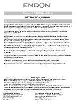
Renner – 5PCH
Brand: Endon Pages: 2

059825
Brand: Toparc Pages: 5

MI-2752
Brand: Mount-It! Pages: 6

HBK-3000
Brand: Crestron Pages: 12

MI-7264
Brand: Mount-It! Pages: 2

Ventry BTV111
Brand: BTECH Pages: 4

ULTRA SLIM WM6010
Brand: One for All Pages: 2


