GBT A2-035 Скачать руководство пользователя страница 9


Page 8


mounted in the lower half of the storage tank. Boiler temperature controls are typically mounted in the primary 
loop. If the temperature control sensor is mounted directly on the heater/boiler water piping, the sensor must be 
installed on the inlet water piping to prevent short cycling of the appliance.  
 
A water flow switch must be installed by the installer  and  wired to prevent the unit from firing if for any reason 
there is an inadequate flow of water through the boiler/heater (see wiring diagrams for suggested location in the 
electrical  circuit). 

NOTE:  CSD-1  model  boilers  only,  are  equipped  with  a  factory  installed  operating 

aquastat.  

 
Optional,  circulation  pumps  can  be  supplied  for  single  or  three  phase  and  115  to  460  volts  as  required.  The 
pump power must be wired independently and should be adequate for the amp rating of the pump motor. Refer 
to  the  Operating  Instructions  and  Wiring  Diagrams  sections  of  this  manual  for  more  information  regarding 
pumps. 


GAS REQUIREMENTS 


Ensure  the  fuel  the  appliance  will  burn  is  the  same  as  that  specified  on  the  boiler 
rating  plate.    Conversions  must  be  completed  by  a  Qualified  Service  Agency  or  Gas 
Provider.    Call  your  Green  Boiler  Technologies  Representative  or  Customer  Service 
for instructions and the proper conversion kit. 

 
The gas supply meter, regulator, and piping must have sufficient capacity to supply all gas fired appliances they 
feed  without  undue  pressure  loss.  If  the  gas  meter,  regulator  or  piping  is  too  small,  request  the  gas  company 
install equipment with adequate capacity. 
 
The  allowable  pressure  loss  in  gas  piping  between  the  gas  meter  or  service  regulator  and  each  appliance  is 
generally between 0.3 to 0.5 inches of water column. Refer to the National Fuel Gas Code, ANSI Z223.1, Latest 
Edition, for sizing guidelines. 


Example: 

For  20  equivalent  feet  of  1-1/2  inch  piping,  the  maximum  cuft/hr  gas  flow  with  a  0.3  inch  w.c. 
pressure  loss  is  726.  For  natural  gas  at  1025  Btu/cuft,  the  maximum  firing  rate  is  744,000  Btu/hr 
[726  x1025].    For  propane  at  2500  Btu/cuft,  the  maximum  firing  rate  is  1,815,000  Btu/hr  [726  x 
2500]. 

 
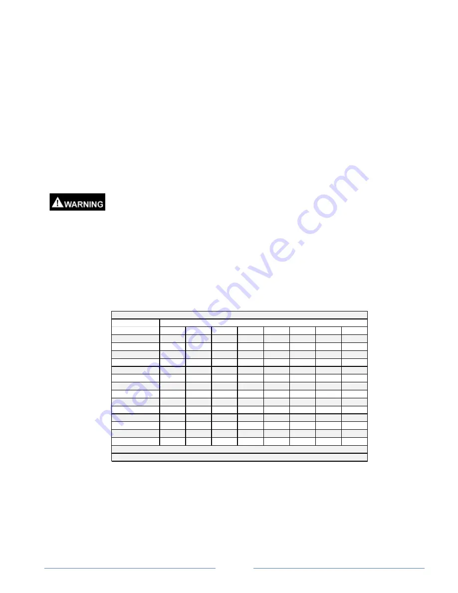
Maximum  and  minimum  gas  pressure  delivered  to  the  boiler/heater  is  shown  below.    If  the  gas  supply  line 
pressure is greater than the maximum listed, a pressure regulator must be installed at least 10 pipe diameters 
upstream of the boiler/heater.   


Max Length

(Equivalent feet)

3/4

1

1-1/4

1-1/2

2

2-1/2

3

4

10

273

514

1060

1580

3050

4860

8580

17500

20

188

353

726

1090

2090

3340

5900

12000

30

151

284

583

873

1680

2680

4740

9660

40

129

243

499

747

1440

2290

4050

8270

50

114

215

442

662

1280

2030

3590

7330

60

104

195

400

600

1160

1840

3260

6640

70

95

179

368

552

1060

1690

3000

6110

80

89

167

343

514

989

1580

2790

5680

90

83

157

322

482

928

1480

2610

5330

100

79

148

304

455

877

1400

2470

5040

125

70

131

269

403

777

1240

2190

4460

150

63

119

244

366

704

1120

1980

4050

175

58

109

224

336

648

1030

1820

3720

200

54

102

209

313

602

960

1700

3460

Gas Pipe Sizing Chart:  Cubic Feet of Gas Per Hour

Size Schedule 40 Metal l ic Pipe (i nches)

Ta bl e  Va l ue s  For Na tura l  Ga s , Spe ci fi c Gra vi ty 0.60

Typical  Natural  Gas = 1025 Btu per cuft ; Typi cal Propane = 2,500 btu/cuft

Содержание A2-035

Страница 1: ...d exactly a fire or explosion may result causing property damage personal injury or death FOR YOUR SAFETY Do not store or use gasoline or other flammable vapors and liquids or other combustible materi...

Страница 2: ...ghly review and understand this manual and perform service and repairs strictly in accordance with the manufacturer s service instructions Gas Supplier A natural gas or propane Utility or service comp...

Страница 3: ...Procedure Operation MAINTENANCE INSPECTION 22 Heat Exchanger Burner Pilot Flame Gas Manifold Pressure Vent System Burner Flue Passageway Pressure Relief Valve High Temperature Switch Flow Switch Heat...

Страница 4: ...ance provides excellent heat transfer and a small footprint The heat exchanger resists build up of lime scale and allows de liming without disassembly of the unit DIMENSIONS SPECIFICATIONS Model A B C...

Страница 5: ...Hot Water Boilers Latest Edition ANSI Z21 10 3 CSA 4 3 Gas Water Heaters Latest Edition All A2000 models are ASME National Board Approved and are constructed in accordance with Section IV of the ASME...

Страница 6: ...must conform to the requirements of the authority having jurisdiction or in the absence of such requirements to the National Fuel Gas Code ANSI Z223 1 NFPA 54 Latest Edition and the National Electric...

Страница 7: ...7 The boiler heater shall be protected from freezing Heat exchangers damaged by freezing shall not be considered for warranty 8 The unit must be located where condensation or leakage from the heat ex...

Страница 8: ...boiler failure Canadian Installations All combustion air must be drawn from outside the building The mechanical equipment room must communicate directly with the outdoors Refer to CGA B149 Installati...

Страница 9: ...too small request the gas company install equipment with adequate capacity The allowable pressure loss in gas piping between the gas meter or service regulator and each appliance is generally between...

Страница 10: ...e gas supply piping must be adequately supported by using hangers or other suitable types of support Do not use the boiler heater gas train to support the gas supply piping The boiler heater and its g...

Страница 11: ...safety device to prevent excessive pressure and temperature Excessive pressure may be caused by the expansion of water when it is heated in a closed system A closed system is one that has a check val...

Страница 12: ...thermometers should be obtained and field installed as shown in the DIAGRAMS section Water Chemistry Water that is very soft very hard having a high total dissolved solids TDS or an acidic or alkaline...

Страница 13: ...ed for outdoor vent sections in cold climates to reduce condensation Observe clearances in accordance with applicable codes from all combustible materials Use insulated venting or vent pipe spacers wh...

Страница 14: ...etween the unit and vent stack from electric meters gas meters regulators and relief equipment no part of the unit or venting may be directly above or below electric meters gas meters or regulators A...

Страница 15: ...as lines feeding the heater boiler were opened to the atmosphere during installation or service air in the gas lines must be purged before operating the unit Before purging gas lines ensure electrical...

Страница 16: ...automatic gas valves NOTE Depending upon the model your heater boiler may be equipped with one or two automatic gas valves 8 Install water temperature measurement thermometers in the water inlet and o...

Страница 17: ...ur qualified service technician or gas supplier 5 Check for gas leaks in the gas train assembly using soap and water or an appropriate leak check fluid DO NOT use an open flame to check for gas leaks...

Страница 18: ...problem with the drafting or make up air o Draft Gauge A draft pressure gauge can be inserted into the vent pipe directly above the draft hood The draft gauge must show a constant negative pressure 12...

Страница 19: ...short cycling Water heaters are expected to operate at temperatures between 120 F and 155 F 49 to 68 o C Water boilers can operate with return water temperature up to 190 F 88 o C and a supply tempera...

Страница 20: ...tch can be changed using the adjustment screw located under the electrical house cover of the switch Rotate the screw clockwise to increase the flow set point counter clockwise to decrease the flow se...

Страница 21: ...5 VAC 115 VAC Impeller 3 7 8 3 7 8 3 7 8 4 5 8 4 3 4 4 3 4 GRUNDFOS UP26 96BF UP43 75BF Not Available Not Available Not Available Not Available Horsepower 1 12 1 6 RPM 3450 3450 Electric 115 VAC 115 V...

Страница 22: ...nd 2 0 inches w c in the LOW fire mode approximately 70 of nameplate input The electronic controller is factory set with both stages in Heating Mode with Stage 2 set for HIGH fire and Stage 1 set for...

Страница 23: ...or incorrect gas manifold pressure Refer to the burner and pilot flame Figure in the START UP Section of this manual Gas Manifold Pressure Check the gas manifold pressure at least once per year to mak...

Страница 24: ...conduct this test Ensure all operating and safety controls are put back into proper operation before putting the heater boiler back into service Flow Switch The water Flow Switch should be checked ann...

Страница 25: ...t fans such as range hoods and bathroom exhausts so they will operate at maximum speed Don not operate a summer exhaust fan Close fireplace dampers d Place in operation the appliance being inspected F...

Страница 26: ...ctrical Power Supplied To the Appliance Should Be Interrupted If The Power Is Not Stopped At The Desired Operating Temperature Correct The Wiring Or Replace The Defective Temperature Switch The Unit W...

Страница 27: ...operly Grounded Remove The Burner Assembly And Inspect The Pilot Burner Assembly Clean Any Residue From The Spark Rod and Striking Plate With a Scotch Brite Pad Use A 1 8 Drill Bit to Make Sure The Ga...

Страница 28: ...ged Cover The Burner And Controls And Clean The Heat Exchanger With A Wire Brush Or High Pressure Water Prevent Future Fouling Of The Heat Exchanger By Preventing Condensation Or Removing Contaminants...

Страница 29: ...Stack Temperature Over 450 o F A Water Temperature Rise Through The Heat Exchanger More Than 5 o F 3 o C Rise Higher Than Originally Set Or Trouble Proving Water Flow Excessive Scaling Inside The Hea...

Страница 30: ...Page 29 DIAGRAMS...

Страница 31: ...Page 30...

Страница 32: ...perature reading at the T P Gauge is about 80 o F higher than the temperature measured at Thermometer A The Heater Boiler must be firing continuously during this adjustment Thermometer readings may be...

Страница 33: ...Page 32 WIRING DIAGRAM A2000 Water Heater Models...

Страница 34: ...Page 33 WIRING DIAGRAM A2000 Boiler Models...

Страница 35: ...Page 34 WIRING DIAGRAM A2000 CSD 1 Boiler Models...

Страница 36: ...Page 35 A2000 WITH CONSTANT PUMP OPERATION A2000 WITH ON OFF PUMP OPERATION...

Страница 37: ...Page 36 A2000 WITH INFITEC PUMP DELAY...

Страница 38: ...Page 37 A2000 PARTS LIST 1 17 19 15 23 22 21 20 18 16 4 2 Gas Train Components Differ By Model 7 14 5...

Страница 39: ...P W5501104 NG Gas Pressure Regulator 1 1 4 RV81 A2 097 NG W5501108 LP Gas Pressure Regulator 1 1 4 RV81 A2 097 LP W5501105 NG Gas Pressure Regulator 1 1 2 RV81 A2 120 140 NG W5501109 LP Gas Pressure R...

Страница 40: ...op Outer Lid Stainless A2 070 W4501021 Top Outer Lid Stainless A2 097 W4501023 Top Outer Lid Stainless A2 120 W4501024 Top Outer Lid Stainless A2 140 16 W4501306 Outer Jacket Stainless A2 035 W4501307...

Страница 41: ...01086 Inner Jacket A2 050 W4501087 Inner Jacket A2 070 W4501089 Inner Jacket A2 097 W4501088 Inner Jacket A2 120 140 23 W5501088 Flue Baffle Cone A2 035 W5501041 Flue Baffle Cone A2 050 W5501040 Flue...

Страница 42: ...surroundings or personal injury resulting from the failure of any control or safety device is not covered under this warranty nor is the liability for such assumed by the manufacturer This warranty c...

Страница 43: ...ty covers only water boilers installed adjusted or maintained in accordance with the installation and operating instructions and all applicable state and local plumbing electrical and building codes o...

Страница 44: ......

Страница 45: ...s and the various gas and electrical connections Make sure the packing slip matches the total number of pieces received If the unit is not to be installed immediately it must be protected from the wea...

Отзывы: