background image

Repair and Adjustment Procedures

Advanced Punch Service Manual

© Copyright 2009 GBC. All rights reserved.

4-69

4.10Belt Replacement

Maintenance Schedule

Inspect every 750K cycles.

Replace as needed.

Procedure

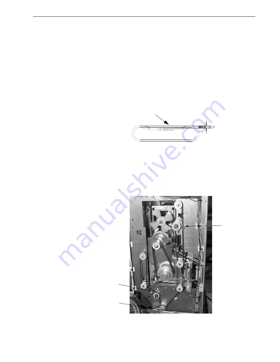
Inspect all timing belts for wear, missing teeth, frayed edges, and cracks. The belts 
should be slightly loose with approximately 1/4” deflection [1]. Belts that are too 
loose will not drive properly and belts that are too tight can wear out prematurely 
or damage their driven components.

Figure 4.79 Typical Belt Deflection.

To replace belts:

1. Loosen the screws of the 3 belt idlers [1].

Installation Note:

When setting the belt tension, adjust the belt idlers so that the 

belt has approximately 1/4" of deflection.

Figure 4.80 Belt Idler Locations.

[1]

[1]

[1]

[1]

Содержание AdvancedPunch

Страница 1: ...Document 7712571 Rev C1 23 08 2013 AdvancedPunch Technical Service Manual ...

Страница 2: ...ved No part of this document may be photocopied or reproduced by any means or translated to another language without prior written consent of GBC All brand names trademarks and registered trademarks are the property of their respective owners Information contained within this document is subject to change without notice ...

Страница 3: ... Die Set Life Expectancy 1 5 Die Set Components 1 5 Serviceable Components 1 6 Die Set Inspection 1 7 Die Set Lubrication 1 8 Hole Alignment Inspection 1 9 Inspection Cleaning and Lubrication 1 10 External Cleaning 1 11 Internal Cleaning 1 11 Operational Inspection 1 11 Internal Inspection 1 11 Base Cleaning 1 12 Chip Bin 1 12 Die Guide Cleaning 1 13 Door Latch Inspection 1 14 Separating Punch Fro...

Страница 4: ...ocedures 2 1 040 101 Fault Diagnosis 2 2 Description 2 2 Initial Actions 2 2 Procedure 2 2 RAP AC Power No Indication of Power 2 3 Description 2 3 Initial Actions 2 3 Procedure 2 3 RAP DC Power No Indication of 24V DC 2 4 Description 2 4 Initial Actions 2 4 Procedure 2 4 RAP Paper Jams at Punch Chad is Present in the Paper Path 2 5 RAP Description 2 5 RAP Initial Actions 2 5 RAP References 2 5 RAP...

Страница 5: ... 4 8 Bypass Idler Roller Replacement 4 13 Punch Idler Rollers 4 15 Idler Roller Removal 4 16 Aligner Panels 4 17 Aligner Idler Roller Replacement 4 17 Aligner Panel Removal 4 18 Aligner Drive Belt Green Belt Replacement 4 20 Paper Entrance Side Green Drive Belt Replacement 4 21 Green Drive Belt Assembly 4 23 Entrance Aligner Panel Installation 4 26 Paper Exit Side Green Drive Belt Replacement 4 27...

Страница 6: ...ocedures 6 2 Entering and Exiting Maintenance Diagnostic Tools Mode 6 2 Component Control 6 2 NVM Read Write 6 3 Adjustments and Feature Control General Procedures 6 4 GBC AdvancedPunch Input Component Control 6 5 GBC AdvancedPunch Output Component Control 6 6 GBC AdvancedPunch NVM Setting List 6 7 GBC AdvancedPunch Fault Code List 6 8 Tools 6 9 Lubrication 6 9 Principle of Operation 6 10 Inputs 6...

Страница 7: ...ved v Table of Contents Communication Cable 7 8 Boot Load 7 9 24 Volts Output 7 10 Steppers 7 11 Overlay 7 12 Sensor Inputs Config 7 13 PCB Assembly 7 14 Section 8 Installation and Set Up 8 1 Installation 8 2 Space Requirements 8 10 Unpacking 8 11 Test Operation 8 11 ...

Страница 8: ...death or serious Injury Warning Risk of electrical shock This warning statement indicates situations where there is a risk of death by electric shock Caution This notice indicates a potentially hazardous situation which if not avoided may result in minor or moderate injury It may also be used to alert against unsafe practices Certain components in this product are susceptible to damage from electr...

Страница 9: ...tching without tools or levers Advanced Punch die sets are available in all of the most common hole patterns and include an Identifying Label providing user with the hole pattern and name Convenient storage area for three extra Die Sets located above the sheet bypass Accurate hole punching with consistent alignment With each Advanced Punch the customer receives a user manual They are encouraged to...

Страница 10: ... 60 70 of their overall workflow Recommended punching limit to 200K sheets per month 600k sheets in bypass mode Die Sets will decrease in performance over time based on the types of stocks and weights that are being punched The expected life of a dieset is 500K punches However if paper stock punched is typically 20 lb bond then up to 2 million punches can be achieved Should be regarded as a long t...

Страница 11: ... x 0 214 L xW Center to Center Hole Spacing 12 7 mm 0 500 For Color Coil Binding choose from C4 Coil Round 4 Holes per inch Hole Size 4 4mm 0 174 Diameter Center to Center Hole Spacing 6 3mm 0 2475 For Velo Bind choose from VB Velobind Round 1 Hole per inch Hole Size 3 2mm 0 125 Diameter Center to Center Hole Spacing 25 4mm 1 For Velo Bind choose from For Looseleaf Binding choose from 3 Ring Binde...

Страница 12: ... 4 Holes per inch Hole Size 4 5mm 0 177 Diameter Centre to Centre Hole Spacing 6 3mm 0 248 For Velo Binding 23 VB Velo Bind Round 1 Hole per inch Hole Size 3 2mm 0 126 Diameter Centre to Centre Hole Spacing 25 4mm 1 2 1 1 4 W3 Wire Square Australia 3 Holes per inch Hole Size 4mm x 4mm 0 158 x 0 158 L x W Centre to Centre Hole Spacing 8 5mm 0 335 W2 Wire Square Australia 2 Holes per inch Hole Size ...

Страница 13: ...y as it relates to curl and identify if any media changes correlate with the emergence of the customer issue 2 Estimate the cycle life on the Die Sets Determine if any of the Die Set life cycles have exceeded 500k sheets cycles 3 Determine if the customer uses only one Die Set pattern style or if they switch between different patterns 4 Determine the last time the Die Set was lubricated 5 Determin...

Страница 14: ... the screen to clear the paper jam If the screen shows a paper jam in the punch follow this sequence To clear a paper jam in the punch 1 Open the punch cabinet door 2 Ensure the Chip Bin is not overflowing 3 Turn punch knob 1 anticlockwise until the punch is in its home position 2 Figure 1 1 Setting the Punch to Its Home Position 4 Open the Bypass panel cover 1 and check for obstructions in the By...

Страница 15: ...2009 GBC All rights reserved 1 3 7 Open the entrance paper Aligner panel latch 1 and clear obstructions in the Aligner 8 Open the exit paper Aligner panel latch 2 and clear obstructions in each Aligner Figure 1 3 Checking Paper Path Through the Punch 1 2 ...

Страница 16: ... channel 2 and clear the path Figure 1 4 Opening the Bottom U Channel 10 When all the paper is cleared close the U channel Aligner Panels and Bypass 11 Shut the cabinet door 12 Verify on the printer screen that the paper jam has been cleared If not repeat the above steps 13 Press the resume button on the printer The printing operation should resume 1 2 ...

Страница 17: ... cycles sheets of paper punched With periodic lubrication and optimum paper types life can exceed this number Access GP6 1 to read the counter for the GBC module Variables that affect life expectancy Failure to follow the lubrication schedule or using the incorrect lubricant Variety and types of paper being punched Cover stocks being punched Length of the average job Other environmental conditions...

Страница 18: ...Section 1 1 6 Copyright 2009 GBC All rights reserved Advanced Punch Service Manual 1 3 2 1 Serviceable Components Punch pins 1 Felt pad on some Die Sets 2 Figure 1 5 Die Set Serviceable Components 2 1 ...

Страница 19: ...ooth operation The top plate and pins should retract fully when you release Figure 1 6 Check For Free Movement Reinstall the Die Set into the punch and run several sheets of the customer s paper through the punch Inspect the holes Holes should be clean and even with no tearing or frayed edges Holes should be punched completely leaving no chip attached Holes should be straight no skew and evenly sp...

Страница 20: ...maintenance between technician inspections Figure 1 7 Inspect Punch Pins To lubricate Die Set pins that do not have felt pads 1 Depress the Die Set so that the pins protrude from the bottom plate 2 Apply a drop of high quality machine oil to the end of each pin 3 Wipe clean leaving a light coat of oil on them To lubricate Die Set pins that have felt pads Lubricate with a high quality machine oil A...

Страница 21: ...Maintenance Advanced Punch Service Manual Copyright 2009 GBC All rights reserved 1 9 Figure 1 8 Die Set Lubrication Points 1 2 ...

Страница 22: ...ms 750K cycles Page 1 25 Inspect Back gauge mechanism 750K cycles Page 1 19 Inspect and clean Vacuum Base 750K cycles Page 1 12 Clean Vacuum Die guide 750K cycles Page 1 13 Clean Vacuum Door closing latch 750K cycles Page 1 14 Inspect Drive rollers 750K cycles Page 1 24 Inspect and clean Alcohol rag Hole alignment 750K cycles Page 1 9 Inspect Idler rollers 750K cycles Page 1 20 Inspect and clean A...

Страница 23: ...cal components Use a vacuum cleaner if possible A small paintbrush can also be used but extreme care should be used around electrical components Non electrical components may be cleaned with alcohol an approved cleaner or a soft cloth moistened with mild detergent and warm water Rollers can be cleaned with alcohol Warning Make sure you disconnect the Advanced Punch from its power source before cle...

Страница 24: ...ure Chips and paper dust falls to the bottom of the punch Clean with a vacuum cleaner each time the machine is serviced The customer can also do this between the technician s visits 1 4 5 1 Chip Bin Remove the Chip Bin and empty Vacuum out paper chips and dust from the Chip Bin tray 1 especially at the back around the Chip Bin micro switch 2 1 2 Front Side ...

Страница 25: ...h Service Manual Copyright 2009 GBC All rights reserved 1 13 1 4 6 Die Guide Cleaning Maintenance Schedule Clean every 750K cycles Procedure Remove the Die Set and clean the guide 1 with a vacuum cleaner Figure 1 9 Die Guide 1 ...

Страница 26: ... Schedule Inspect every 750K cycles Procedure Ensure latch holds door closed Ensure switch is activated when the door is closed To adjust the door latch see Door Latch on page 4 5 Figure 1 10 Door Switch Tab and Switch 1 4 8 Separating Punch From Printer Some procedures require separating the Advanced Punch from the printer and finisher Refer to Separating the Punch From the Printer on page 4 1 1 ...

Страница 27: ...edule Clean every 750K cycles Procedure Inspect for worn or damaged parts Clean with alcohol an approved cleaner or a soft cloth moistened with mild detergent and warm water as needed To clean the Aligner Panels 1 Lift the Aligner latches to open panels 2 Clean surfaces 1 3 Clean paper alignment channels 2 Figure 1 11 Aligner Panel Components 1 2 ...

Страница 28: ...ery 2000K cycles Procedure Make sure the aligner rollers are clean Ensure that the idler rollers maintain pressure against the green drive belt Inspect for bent or damaged parts Warning Disconnect the Advanced Punch from power and retain the power cord in your possession for your safety Failure to observe this warning could result in death or serious Injury To inspect the aligner idler rollers 1 P...

Страница 29: ... the torsion springs 1 are hooked over the bracket 2 Figure 1 13 Aligner Roller Torsion Spring Hooked on Bracket To clean idler rollers 1 Clean the idler rollers with a soft cloth and alcohol 2 Inspect the idler rollers for wear patterns or groves Surface should be evenly textured and clean 1 2 ...

Страница 30: ... every 4000K cycles Procedure Ensure the Green Drive Belts are clean Inspect for frayed edges and wear To clean the Green Drive Belts 1 Clean Green Drive Belt 1 with a plastic scouring pad or 3M Scotchbrite Pad 2 Use the drive knob 2 to turn the belt Figure 1 14 Cleaning Green Drive Belt To adjust or replace the Green Drive Belt see Aligner Drive Belt Green Belt Replacement on page 4 20 1 2 2 ...

Страница 31: ...solenoid linkage moves freely Press linkage down and release 1 Linkage should return Clean out the solenoid and surrounding area with a vacuum cleaner and canned air 2 Make sure the solenoid is clean and dry Note Do not apply lubricants to the solenoid or linkage To remove and inspect the back gauge see Back Gauge Assembly on page 4 36 and Back Gauge Removal on page 4 37 Figure 1 15 Inspect and Cl...

Страница 32: ...e paper through the bypass 1 or the punch 2 Maintenance Schedule Inspect and clean every 750K cycles Replace idler rollers every 2000K cycles See Page 4 13 Procedure Inspect rollers for wear patterns or groves The roller surface should be even and have a textured surface Where practical remove the roller assembly to clean 3 See Idler Roller Removal and Cleaning on page 1 21 2 3 3 3 1 ...

Страница 33: ...aining spring over the end of the idler roller shaft The illustration shows moving the spring 1 on the bypass plate which has been removed from the machine for clarity 4 Pull the released shaft end out of the bushing fork 2 releasing the opposite end of the shaft from the other retaining spring 5 Clean the idler rollers with a soft cloth and alcohol 6 Ensure the rollers turn freely on the shaft th...

Страница 34: ...ller Cleaning Some idler rollers 1 2 are not easily removed but can be cleaned while in the punch To clean non removable idler rollers 1 Separate the punch from the printer 2 Disconnect the power 3 Pull out the chip bin to access idler roller 1 4 Inspect and clean idler rollers 1 2 with a soft cloth and alcohol 1 2 ...

Страница 35: ...Maintenance Advanced Punch Service Manual Copyright 2009 GBC All rights reserved 1 23 5 Use the drive 1 knob to turn the rollers to continue inspection and cleaning 1 ...

Страница 36: ...ct and clean every 750K cycles Procedure Inspect for wear patterns or groves The roller surface should be even and not glazed Some drive rollers are not easily accessible Those that are 1 should be inspected and cleaned when the idler rollers are removed Where practical make sure the rollers are clean Clean with a soft cloth and alcohol See also Idler Roller Inspection and Cleaning on page 1 20 1 ...

Страница 37: ... hold the Aligner Panels in place which in turn keeps even pressure on the idler rollers Maintenance Schedule Inspect every 750K cycles Procedure Inspect the latches for worn or damaged parts Open and close the latches and ensure they lock into place when closed Ensure the nylon wheel 2 turns freely on its bearing and that it aligns with its locking 1 2 ...

Страница 38: ...ts reserved Advanced Punch Service Manual 1 4 15 Optical Sensor Cleaning Maintenance Schedule Clean every 750K cycles Procedure Inspect and clean per the maintenance schedule or as needed Supplies Needed Canned air or vacuum cleaner 1 1 1 1 1 1 ...

Страница 39: ...Maintenance Advanced Punch Service Manual Copyright 2009 GBC All rights reserved 1 27 Use canned air to blow the debris off each sensor The illustration shows examples of three sensors 1 1 1 1 ...

Страница 40: ...oves The surface should be rough and even Make sure the rollers are clean Clean rollers with a soft cloth and alcohol See also Idler Roller Inspection and Cleaning on page 1 20 and Drive Roller Inspection and Cleaning on page 1 24 Raise the panel and ensure the magnet holds it in open 4 Inspect the path for obstructions Clean as needed Close the panel and check that it is flat and that paper will ...

Страница 41: ...0K cycles Procedure Inspect the entire paper path through the punch Look for wear damage and obstructions Inspect the rollers for wear patterns or groves Open the Aligner Panels 1 and U channel 2 and make sure there are no obstructions Confirm that the latch holds the U channel Loop Pivot Paper Guide Assembly tightly in place 2 If the latch is bent or damaged replace the U channel See PL 5 3 item ...

Страница 42: ...ntenance Schedule Lubricate with a PTFE based grease per schedule see Table 1 2 Customer Maintenance on page 10 Procedure The Back Gauge assembly must be removed in order to lubricate the punch cams To remove the punch see Punch Module Removal on page 4 49 To lubricate the cams see Punch Drive Cam Lubrication on page 4 54 ...

Страница 43: ...ng teeth frayed edges and cracks For replacement see Belt Replacement on page 4 69 Check for proper deflection of belts The belts should be slightly loose with approximately 1 4 deflection 1 Belts that are too loose will not drive properly and belts that are too tight can wear out prematurely or damage their driven components Five belts have tensioners it is these five belts that should be checked...

Страница 44: ...ment 3 Using the customer s primary Die Set pattern run 200 duplex printed test sheets through the punch mode and examine the output for clean hole quality and even hole alignment 4 Using any of the customer s secondary Die Set pattern run 100 simplex printed test sheets through the punch mode and examine the output for clean hole quality and even hole alignment 5 Run 100 sheets simplex and 100 sh...

Страница 45: ... 2009 GBC All rights reserved 2 1 Section 2 Fault Analysis Procedures Also called Repair Analysis Procedures this section contains the basic troubleshooting information that a technician needs to isolate the root cause of a specific symptom ...

Страница 46: ...hly saturated images and no paper Perform Tag 1 upgrade Replace S2 Sensor Shutdowns in Entrance Aligner and punch area First jammed sheet is in punch area next sheet overlaps first Slippage at E roller Check aligner idler springs for correct position Check for freedom of motion of E roller idler shaft roller in the retainers Clean contamination from Aligner belts and E rollers Dieset is worn Use a...

Страница 47: ...sconnect the communication cable then remove the rear covers to gain access to the electrical components at the rear of the machine Warning AC Voltage are dangerous Use extreme care when checking 2 Connect the power cord and switch ON the main power 3 Measure for line voltage at the Receptacle Filter You have line voltage Yes Go to the next step No Replace the Receptacle Filter 4 Measure for line ...

Страница 48: ...e next step No Replace the Cable to the Power Supply Board 3 Measure for 5V DC at pin 3 of the Communication Cable There is 5V DC at the connection Yes Go to the next step No Replace the Communication Cable 4 Measure for 5V DC at J13 of the Main Control Board There is 5V DC at the connection Yes Go to the next step No Replace the Main Control Board 5 Measure for 5V DC at the other end of J13 There...

Страница 49: ...e Set any pattern Run several more sheets to confirm the symptom 2 4 3 RAP References Die set maintenance section 1 3 2 4 4 RAP Procedure 1 Inspect the die set that results in frequent paper jams The oil pad pins or shoulder bolt lubrication appears to be dried away Y Perform the lubrication procedures explained in section 1 3 N Go to the next step 2 Inspect the die set shoulder bolts for straight...

Страница 50: ...erences Back gauge solenoid inspection and cleaning section 1 4 11 Back gauge Assembly section 4 8 2 5 4 RAP Procedure 1 Disconnect the system from the printer train to access the input side of the punch Inspect the back gauge solenoid area Excessive chad build up is apparent Y Perform the cleaning procedure explained in section 1 4 11 N Go to the next step 2 Inspect the back gauge solenoid area O...

Страница 51: ...Drive Roller One or both of the retaining springs are loose or missing or the Energy Drive Idler Roller is not freely moving in the retainers Y Reconnect or replace the retaining spring and ensure the idler roller is making good contact with the drive rollers or reform the retainers to reduce interference with the roller assembly N Go to the next step 2 Inspect the surface of the rollers The rolle...

Страница 52: ...rol board a minimum of 2 of the 3 LEDs on this board should be lit if not board is bad Replace main control board Display panel or cable Inspect or replace Door not making interlocks Inspect or replace Die Set not making switch Inspect or replace Communication cables between Advanced Punch and Printer Check communication cables between printer and Advanced Punch Indication of power yet Advanced Pu...

Страница 53: ...ain control board Adjust or replace AC punch motor Adjust or replace Paper jam and or punch shaft does not return to the home position Punch brake is not performing properly Adjust or replace Paper jam and or punch continues to cycle Flag sensor is broken or misaligned Adjust or replace Paper will not enter the punch area runs through bypass only Divert solenoid malfunction Adjust or replace Paper...

Страница 54: ... springs Replace the spring See Solenoid Spring Replacement on page 4 46 Solenoid plunger stuck Clean the solenoid See Back Gauge Solenoid Inspection and Cleaning in Section 1 4 11 Solenoid plunger worn Replace Back Gauge See Back Gauge Assembly in Section 4 8 Punches occur 2 to 4 into the sheet One or more broken or missing linkage springs Replace the Back Gauge assembly as explained in section 4...

Страница 55: ...djustment procedure explained in Section 4 11 Figure 3 1 Hole Alignment on Finished Sheet 3 2 RAP Hole Skew Check This RAP explains the procedure to follow when the holes in the paper are not in alignment along the margin of the paper One end is further from the edge than the other end as shown in Figure 3 2 1 Inspect the Back Gauge Solenoid It is free of Chad build up N Clean the chad following p...

Страница 56: ...uality of the punched paper output Under a general inspection the holes are cleanly cut and free of hanging chad No Go to Section 1 3 Die Set Service and perform the maintenance checks and lubrication 3 4 RAP Oil On Paper Inspect the paper around the punched holes Under a general inspection there is not an oil residue around the holes No Reference section 1 3 Die Set Service and perform the mainte...

Страница 57: ...oller Pinch Rollers This procedure will assist you to identify the source of the damage and to perform corrective actions Procedure 1 Review problem with the customer request that the customer reproduce the problem to fully understand the materials workflow and run modes involved 2 Run 50 100 sheets into a single stack and compare the defect with the photos below Figure 3 3 Damage from Exit Pinch ...

Страница 58: ... areas aligning with each Backgage Gate Corrective actions Check replace pinch roll mounting and spring locations especially those located in the Entrance Aligner and E Roller areas roller immediately before the Backgage Assembly Clean all pinch roller Aligner Belts and E Rollers with mild soapy water and rinse with a damp lint free towel Check punch die by exchanging with another punch die if ava...

Страница 59: ...ated from the printer and finisher and the rear cover be removed Warning Disconnect the unit from power and maintain the cord in your possession Failure to observe this warning can result in injury or electrical shock Procedure Unplug the unit from power Disconnect the communication cable Empty Chip Bin 4 1 1 Separating the Punch From the Printer Follow the instructions as described in the printer...

Страница 60: ...Punch From the Printer in Section 4 1 Note It is not necessary nor recommended that you remove the top cover Procedure Tool Required Phillips screwdriver or 1 4 hex head nut driver To remove the rear cover 1 Remove the 5 screws on the entrance side 1 remove the 4 rear cover screws 2 2 Slide the cover out from under the top cover Do not remove the top cover Figure 4 1 Removing Rear Cover 2 1 ...

Страница 61: ...Note It is important that the punch is not twisted or skewed It must be level front to back and side to side Procedure Raise or lower the Advanced Punch s castors to level it Tool Required Tool located on front door 2 3 8 open ended wrenches Level To level the punch 1 Remove the rear cover and put the punch back in line with the printer and finisher 2 Place the level on a flat surface of the top 1...

Страница 62: ... nut 1 of the castor Figure 4 3 Castors Locking Nuts 4 From below the frame and at the top of the castor 2 adjust the height of the castor as needed 5 Check the level and adjust as necessary 6 Tighten the locking nut 1 7 Ensure punch is level and in line with printer and finisher 8 Replace rear cover 1 1 ...

Страница 63: ...oor closed and that the activating bracket tab 1 depresses the door switch 2 The tab should press the switch button just so that it is close to bottoming out Figure 4 4 Door Latch and Switch 4 3 1 Door Latch Adjustment To adjust the door latch 1 Open the front door 2 Loosen the two adjustment screws 1 on the door latch Figure 4 5 Door Latch Adjustment Screws 1 2 1 ...

Страница 64: ...in move the latch towards the front of the door To move the door out move the latch away from the front of the door 4 Tighten the 2 screws 1 and close the door 5 Test its operation 4 3 2 Door Latch and Switch Replacement To replace the door latch 1 Open the front door 2 Remove the 2 screws 1 Figure 4 6 Door Latch and Screws 1 ...

Страница 65: ...nt Procedures Advanced Punch Service Manual Copyright 2009 GBC All rights reserved 4 7 To replace the door switch 1 Open the front door 2 Remove the 2 screws 1 3 Unplug connectors from switch 2 Figure 4 7 Door Switch 2 1 ...

Страница 66: ...driver Flat bladed screwdriver Needle nose pliers Procedure Separate the punch from the printer and remove the rear cover See Section 4 1 and Section 4 1 2 4 4 1 Bypass Panel Removal To remove the Bypass panel 1 Disconnect the grounding strap by removing the screw on the exit side of the bypass 1 2 Unplug the exit side sensor at the rear frame 2 Figure 4 8 Disconnect the Grounding Strap and Unplug...

Страница 67: ...Manual Copyright 2009 GBC All rights reserved 4 9 3 Unplug the entrance side sensor at the rear frame 1 Figure 4 9 Sensor Connector on Entrance Side 4 From the rear of the punch remove one of the E rings from the Bypass shaft 1 Figure 4 10 Remove E Ring 1 1 ...

Страница 68: ...ther end of the shaft clears the nylon bushing and bracket 6 Lift the opposite end of the shaft 3 and slide it out of the Bypass panel in the opposite direction of the removed E Ring 4 Installation Note Make sure the nylon bushing is installed so that it protrudes through the mounting bracket of the rear frame into the Bypass panel 5 Figure 4 11 Bypass Panel Shaft and Rear Frame 5 2 5 4 1 3 ...

Страница 69: ...anced Punch Service Manual Copyright 2009 GBC All rights reserved 4 11 7 Rotate the rear of Bypass panel 1 so that it extends past the entrance side of the punch 2 Figure 4 12 Rotate the Bypass Panel Out the Entrance Side of the Punch 2 1 ...

Страница 70: ... new panel this includes sensors springs cables and rollers 9 To install the Bypass panel reverse the steps Installation Note Before installing the new bypass panel into the machine ensure that all rollers move freely within the guides in the panel Adjust the guide fingers as nessecary to obtain free travel Position the Bypass panel so that it is outside the shaft mounting brackets The nylon bushi...

Страница 71: ... can be serviced without removing the Bypass panel Maintenance Schedule Inspect and clean every 750K cycles Refer to Refer to Section 1 4 12 1 Replace idler rollers every 2000K cycles Procedure Inspect rollers for wear patterns or groves The roller surface should be even and have a textured surface Replace when needed or per the maintenance schedule Rollers bushings and shaft are replaced as one a...

Страница 72: ...he released shaft end out of the bushing fork 2 releasing the opposite end of the shaft from the other retaining spring 3 To install idler roller assemblies reverse the steps Installation Note Make sure the flat surface of the bushing aligns in the fork Rollers are non directional so it does not matter which end goes in each fork After the assembly is in place gently pull the assembly outward and ...

Страница 73: ...m the printer Refer to Separating the Punch From the Printer on page 4 1 Maintenance Schedule Inspect and clean every 750K cycles Refer to Idler Roller Inspection and Cleaning on page 1 21 Replace idler rollers every 2000K cycles Procedure Inspect rollers for wear patterns or groves 1 The roller surface should be even and have a textured surface Replace per the maintenance schedule Idler Rollers o...

Страница 74: ...over the end of the idler roller shaft Figure 4 17 Releasing Idler Roller Retaining Spring 2 Pull the released shaft end out of the bushing fork 2 releasing the opposite end of the shaft from the other retaining spring 3 To install idler roller assemblies reverse the steps Installation Note Make sure the flat surface of the bushing aligns in the fork Rollers are non directional so it does not matt...

Страница 75: ...ide Aligner panel positions the paper for the finisher Prior to servicing the Aligner Panels separate the Advanced Punch from the printer Refer to Separating the Punch From the Printer on page 4 1 4 6 1 Aligner Idler Roller Replacement Maintenance Schedule Clean every 750K cycles Refer to Idler Roller Inspection and Cleaning on page 1 21 Tools Required Flat head screw driver Needle nose plyers Pro...

Страница 76: ...e Aligner Green Drive Belt The procedure is the same for the entrance and exit Aligner panels except that the exit side has a docking plate which must be removed first To remove the Aligner panel 1 Release the Aligner latch 1 2 Remove the E clips from both ends of the Aligner shaft 2 3 Slide the shaft out the front of the punch Figure 4 19 Entrance Side Aligner Panel 3 2 3 2 1 5 ...

Страница 77: ...ghts reserved 4 19 4 Remove aligner latch stop by removing screws 4 5 Remove the shaft nylon bushings 3 6 Lift the Aligner panel up and unhook the tension spring from the panel 5 7 Remove the Aligner panel out the front of the punch 8 Reverse the steps to install the Aligner panel 4 5 3 3 ...

Страница 78: ... or exit side green drive belt service Paper Entrance Side Green Drive Belt Replacement on page 4 21 or Paper Exit Side Green Drive Belt Replacement on page 4 27 Tools Required Phillips screw driver Nut drivers 1 4 and 5 16 Hex wrenches 5 64 and 9 64 Snap ring pliers E Ring tool Twelve inch metal ruler or similar straight edge Caution Disconnect the Advanced Punch from power and retain the power c...

Страница 79: ...ance Side Green Drive Belt Replacement Figure 4 20 Opening Door and Removing Chip Tray 1 Disconnect the entrance sensor wire from the side frame 1 2 Remove the 4 screws that secure the front paper chute 2 Figure 4 21 Remove 4 Paper Chute Screws 3 To remove the GP2 aligner latch 9 do the following 1 ENTRANCE SIDE EXIT SIDE 2 2 ...

Страница 80: ...ings from the Pivot shaft 3 b Slide the shaft 3 all the way out through the front of the Advanced Punch c Remove the fan 4 that prevents access to the flexible cable To remove it simply pull it off of the shaft d Remove the flexible cable using a hex wrench e Remove the rear top motor pulley 5 f Loosen the belt 6 g Remove the belt and pulley h Loosen screw from the solenoid link i Remove the solen...

Страница 81: ...age the wiring 6 Remove the green drive belt Aligner Roller assembly by removing the 4 screws S Caution Leave the Flex Shaft FS attached Figure 4 23Removing the green drive belt 4 6 3 2 Green Drive Belt Assembly 1 Stretch the new Belt B onto the Aligner Roller assembly green side out Rotate the Shaft S to confirm that the belt tracks properly 2 Slide the Aligner into place loosely attach the 4 Pan...

Страница 82: ...ket at the top left Be sure that the Flex Coupling Shaft is sticking out of the rear of the GP 501 Punch properly b Visually check all around the mounting area of the Paper Guide assembly and that the Sensor Harness is properly connected c Loosely secure it in place with 3 screws on the left and 3 on the right d Loosely install the 2 top screws e Once all 8 mounting screws have been properly start...

Страница 83: ... 2009 GBC All rights reserved 4 25 Figure 4 25 Installing J2 Shaft 8 Close the Flipper Latch Repeat the test of rotating the pulleys to ensure smooth rotation of the Idler Rollers 9 Attach the Shaft Spring 10 Install the front E Ring to secure INSTALL J2 SHAFT ASSEMBLE BACK ...

Страница 84: ...el refer to Back Gauge Solenoid Inspection and Cleaning on page 1 20 Then insert the punch into the printer and finisher and connect the power cord Test the Advanced Punch by doing the following 1 Run10 copies in bypass mode 2 Run 1 sheet in punch mode 3 Run 10 sheets in punch mode 4 Run 100 sheets in punch mode Figure 4 26 Removing Rear Aligner AFTER ASSEMBLY ...

Страница 85: ... Idler Paper Guide assembly a Remove 2 E Rings from the Pivot Shaft b Slide the Shaft all the way out through the front of the Advanced Punch c Remove the 2 nylon bearings d Remove and set aside the Rear Aligner Idler Paper Guide assembly 3 To remove the curved sheet metal Exit Paper Guide assembly a Remove the 4 screws 2 rear and 2 front of the curved sheet metal Exit Paper Guide assembly b Unplu...

Страница 86: ... this assembly from the top d Pull and walk the entire sheet metal assembly of the Paper Guide Aligner up and outward You can grab the assembly at the roller cut out with your fingers Caution Handle the helical coupling carefully It is very delicate Note In order to access these screws you must first remove the Die Set storage shelf and the cable shield attached to the Die storage shelf at the pap...

Страница 87: ...onnect the sensor harness behind the assembly as soon as you are able to reach it Failure to do this can damage the unit 5 Remove the green drive belt Aligner Roller assembly by removing the 4 screws S Caution Leave the Flex Shaft FS attached 6 Remove the green drive belt Aligner Roller assembly by removing the 4 screws Caution Leave the Coupler attached ALIGNER DRIVE BELT ASSY ...

Страница 88: ... to confirm that the belt tracks properly 2 Slide the Aligner into place loosely attach the 4 pan head screws with the 4 lock washers Figure 4 30 Installing Green Drive Belt Check that the metal surface of the Aligner Roller assembly is flush with the sheet metal surface of the Paper Guide A 12 metal ruler works well to check this adjustment Slip the ruler under the green drive belt and press it f...

Страница 89: ...reen drive belt should look like the drawing shown in Figure 4 30 To ensure proper assembly hold the entire Paper Guide assembly up so that you can visually inspect the alignment between the sheet metal surface and the metal surface of the Aligner The green drive belt should appear to be even and just floating above the surface of the sheet metal ALIGN FIX SCREWS ...

Страница 90: ...harness is properly connected c Loosely secure it in place with 3 screws on the left and 3 on the right d Loosely install the 2 top screws e Once all 8 mounting screws have been properly started go back and tighten the screws until they are snug Caution Do not over tighten the 2 screws on top 4 Install the 2 screws to secure the bearing block for the pulley arrangement at the rear of the Advanced ...

Страница 91: ...o place through both pieces of sheet metal with the flange to the inside c Slide the shaft through the front of the machine while holding the nylon flange bearing in place d Secure with 2 E rings on the inside of the bearing e Inspect by pressing in on the bottom area of the sheet metal for A slight deflection of each Idler Roller as you press As you press you can turn the pulleys at the rear of t...

Страница 92: ... Aligner panel refer to Back Gauge Solenoid Inspection and Cleaning on page 1 20 Then insert the punch into the printer and finisher and connect the power cord Test the Advanced Punch by doing the following 1 Run10 copies in bypass mode 2 Run 1 sheet in punch mode 3 Run 10 sheets in punch mode 4 Run 100 sheets in punch mode AFTER ASSEMBLY ...

Страница 93: ... from its mounting bracket 2 Lift the shaft 2 from the mounting bracket 3 Using a clean cloth and alcohol clean the surfaces of the rollers 3 to remove any paper dust or toner that may have accumulated over time 4 Reverse steps 2 1 above to replace the shaft into the holder 5 Ensure the flats of the bearings are seated properly in the mounting brackets 6 Ensure the springs are straight on the bear...

Страница 94: ...ect the Advanced Punch from its power source before removing the Back Gauge assembly Failure to observe this warning can result in severe injury or death and damage the punch Maintenance Schedule Clean every 750K cycles Replace every 3 000K cycles Procedure Remove Back Gauge assembly to clean and service the solenoid or to replace the Back Gauge Also allows the removal of the Punch Module To repai...

Страница 95: ...uge Removal To remove the Backgage assembly 1 Begin by removing the punch dieset and the chip bin waste container 2 Remove rear cover as well as the rear entrance side cover Figure 4 34 Rear Cover Rear Entrance Side Cover Removal 3 Remove the four screws securing power supply plate Figure 4 35 Power Supply Plate Removal ...

Страница 96: ... 36 Exposure to Circuit Board 5 Locate and then disconnect wire harness J8 from the circuit board Wire harness J8 consists of two black wires Figure 4 37 J8 Connector Removal Note On A4 230VAC 50Hz models the AC line filter is larger then on the LTR 60Hz model Because of this the AC line filter must be removed when performing this procedure on an A4 model machine ...

Страница 97: ... Removal of AC Line Filter 6 To remove wire harness J8 from the other cables it will be necessary to cut and discard some wire ties Take caution not cut or damage any wires while performing this action After the wire ties are removed undress wire harness J8 from the other cables Figure 4 39 Separating Backgage harness ...

Страница 98: ...arness J8 Figure 4 40 Release Harness J8 8 Locate the black rubber grommet that harness J8 passes through Remove the grommet from its mounting hole in the frame by pushing from one side and pulling from the other Once the grommet is removed from the frame pass wire harness J8 completely through the hole so that it is free of the frame Figure 4 41 Removal of Grommet ...

Страница 99: ...ght 2009 GBC All rights reserved 4 41 9 Remove the two screws securing the backgage chute then remove the chute Figure 4 42 Removal of Backgage Chute 10 Remove the two screws securing the dieset brush then remove the brush and bracket Figure 4 43 Removel of Brush Bracket ...

Страница 100: ...nced Punch Service Manual 11 Remove punch module home sensor cable Figure 4 44 Removal of Sensor Cable 12 Remove the two screws shown below from the dieset stop bracket and then remove the bracket from the rear frame Figure 4 45 Removal of Dieset Stop Bracket ...

Страница 101: ... All rights reserved 4 43 13 Remove the two screws that secure the backgage to the rear frame Figure 4 46 Removal of Backgage Screws 14 Remove the backgage assembly by swinging it out from the left side and then finally removing the backgage entirely Figure 4 47 Removal of Backgage ...

Страница 102: ...k gauge make certain to save the black grommet from the original back gauge that is referenced in Figure 4 41 Removal of Grommet 4 8 1 2 Testing To test the Back Gauge 1 Install a Die Set 2 Rotate the punch drive knob to ensure the drive and cams turn easily 3 Test for proper hole alignment to the paper edge by doing the following a Run 1 page at a time b Run 2 pages at a time c Run 5 pages at a t...

Страница 103: ...pect for damaged or worn parts The only repairable part is spring replacement See Solenoid Spring Replacement on page 4 46 Replace Back Gauge if solenoid is inoperative To clean the solenoid with the Back Gauge out of the punch 1 Clean with a vacuum cleaner and canned air See also Back Gauge Solenoid Inspection and Cleaning on page 1 20 2 Inspect for dirt or obstructions wear or damage or missing ...

Страница 104: ...tion 4 4 46 Copyright 2009 GBC All rights reserved Advanced Punch Service Manual 4 8 2 1 Solenoid Spring Replacement Procedure Replace broken or missing springs 1 Figure 4 49 Back Gauge Solenoid Springs 1 ...

Страница 105: ...8 3 Back Gauge Paddle Procedure Deep or angled deep punches may be caused by a broken weld on the Paddle 1 shaft Inspect the Paddle and press down on it while holding the linkage to keep the linkage from moving If the paddle moves 2 replace the Back Gauge assembly Figure 4 50 Testing for Broken Paddle Weld 1 2 ...

Страница 106: ...nd small parts that you may drop into the bin Procedure Remove the module to lubricate the cams or to service or replace the following components Drive motor Drive motor belt Brake Cams Flexible drive coupling Punch Module drive rollers The clutch can be replaced without removing the module See Clutch Replacement on page 4 55 Warning Disconnect the Advanced Punch from its power source before remov...

Страница 107: ...ed before removing the Punch Module See Back Gauge Assembly on page 4 36 To remove the Punch Module 1 Remove the Back Gauge assembly 2 Use a 5 64 hex wrench to remove the Punch Cycle knob 1 Figure 4 51 Removing the Punch Cycle Knob on the Front Panel 3 Remove the 4 Punch Module retaining screws from the front panel 1 Figure 4 52 Punch Module Front Retaining Screws 1 1 1 ...

Страница 108: ...on 4 4 50 Copyright 2009 GBC All rights reserved Advanced Punch Service Manual 4 Cut the cable ties on the left wiring harness 1 to free the Punch Module wiring Figure 4 53 Wiring Harness at Rear of Punch 1 ...

Страница 109: ...eserved 4 51 5 Remove the belts in the following order a Remove the bottom left and right vertical belts 1 by walking the belts over the pulleys b Loosen the belt idler rollers 2 and remove the upper vertical belt c Remove the bottom triangular belt 4 Figure 4 54 Order of Belt Removal 4 1 2 3 1 ...

Страница 110: ...nced Punch Service Manual 6 Remove the two rear Punch Module screws 1 Figure 4 55 Punch Module Retaining Screws on Rear of Punch 7 Remove the 4 power supply screws 1 Figure 4 56 Power Supply 8 Cut wire harness ties as needed to release the punch wiring 1 1 1 1 ...

Страница 111: ...ved 4 53 9 Unplug the punch connector 1 from the control board Figure 4 57 Punch Connector on Control Board 10 Carefully slide the Punch Module out the back of the punch Ensure that the wiring harness does not get caught or prevent removal of the module Figure 4 58 Removing the Punch Drive Module 1 ...

Страница 112: ...es with Teflon grease Procedure The Punch Drive module must be removed for service Clean the old grease from the cams and then apply a light coat of high quality grease not oil To remove the module see Punch Module Removal on page 4 49 Figure 4 59 Installation Note Make sure the wires on the rear of the punch are not obstructing the Die Set or Chip Bin Grease cams ...

Страница 113: ...Clutch Replacement Procedure Replace if clutch is malfunctioning Note The clutch can be removed without removing the Punch Module Tools Required Phillips screwdriver or 1 4 nut driver Hex wrench 5 64 To remove the clutch 1 Unplug the flag sensor connector 1 Figure 4 60 Flag Sensor Connector on Rear of the Punch 1 ...

Страница 114: ... All rights reserved Advanced Punch Service Manual 2 Remove the metal spring clip 1 from the fan and slide the fan 2 off the shaft Figure 4 61 Punch Fan and Spring Clip 3 Remove the lower drive belt 1 Figure 4 62 Punch Drive Belt 1 2 1 ...

Страница 115: ...oosen the 2 pulley socket head set screws 1 5 Remove the pulley and its shaft key 2 Figure 4 63 Drive Upper Pulley 6 Remove the 2 clutch bracket screws 1 Figure 4 64 Clutch Bracket Installation Note When installing the clutch bracket ensure that the fork of the clutch engages the tab on the bracket 2 1 2 1 2 1 ...

Страница 116: ...ch Installation Note When installing the clutch be sure to install the shaft key Press the clutch against the drive gear plate While pressing the clutch against the plate tighten the 2 set screws The assembly does not require a gap between the clutch and clutch plate 8 Cut wire ties as needed and unplug the clutch connector 1 from the control board Figure 4 66 Punch Clutch Connector on the Control...

Страница 117: ...anual Copyright 2009 GBC All rights reserved 4 59 9 Slide the back portion of the clutch 1 off the shaft The motor drive belt 2 can be removed at the same time Figure 4 67 Drive Belt and Back Portion of Clutch 10 To install the clutch reverse these steps 1 2 ...

Страница 118: ... drive shaft To adjust the brake see Punch Module Brake Adjustment on page 4 62 Tools Needed Feeler gage 0 010 0 25 mm Hex wrenches 0 05 and 3 32 Flat blade screwdriver Pliers 4 9 4 1 Punch Module Brake Replacement To replace the brake 1 Remove the 4 socket head set screws 1 2 Loosen the 2 set screws 2 until the brake pad 3 slides freely on the shaft Figure 4 68 Brake Assembly and Drive Shaft Inst...

Страница 119: ...09 GBC All rights reserved 4 61 3 Remove the E Ring at the opposite end of the shaft 1 4 Slide the shaft out of the bearing bracket away from the clutch end 5 Slide the brake assembly off the shaft Figure 4 69 Shaft E Ring 6 To install the brake assembly reverse these steps 1 ...

Страница 120: ...thout removing the brake from the shaft The gap between the brake and the pad is 0 010 0 25 mm To adjust the brake 1 Loosen the 2 set screws 2 until the brake pad slides freely on the shaft Figure 4 70 Brake Assembly Gap Adjustment 2 Use a 0 010 feeler gage to set the gap between the brake and the brake pad 3 Tighten the 2 set screws and check the gap 1 0 010 ...

Страница 121: ...wire ties as necessary to release the motor wires 2 Unplug motor wire connections from the capacitor 1 Figure 4 71 Punch Capacitor 3 Remove the metal spring clip 1 from the fan and slide the fan 2 off the shaft Figure 4 72 Punch Fan and Spring Clip Installation Note When installing the fan be sure to align the flat of the fan hub with the flat on the shaft Also make sure the hub and spring clip ar...

Страница 122: ...Advanced Punch Service Manual 4 Loosen the 2 socket head set screws 1 on the pulley and slide the pulley and belt off the shaft 5 Remove the motor mounting 4 nuts 2 Figure 4 73 Motor Pulley and Mounting Nuts 6 To install the motor reverse these steps 2 2 1 ...

Страница 123: ...he belt when it is frayed missing teeth or worn out To replace the Punch Module drive belts 1 With the fan removed from the shaft work the belt 1 off the clutch gear 2 Figure 4 74 Motor Pulley and Belt 2 Install a new belt by looping it over the motor pulley and then work it onto the clutch gear The belt requires no adjustment It should have slight deflection when pressed 2 1 ...

Страница 124: ... a soft cloth and alcohol Tools Required Phillips screw driver or 1 4 nut driver Flat bladed screwdriver Needle nose pliers Remove the Punch Module Assembly first using procedure Punch Module Removal on page 4 49 With the Punch Module out of the machine the punch entrance side 1 and exit 2 drive rollers can be cleaned or replaced Figure 4 75 To clean the punch entrance drive rollers 1 Remove the i...

Страница 125: ...rance drive rollers 1 Unplug the sensor 1 2 Remove the 2 screws at the ends of the idler roller assembly 2 3 Remove the 2 screws at the ends of the drive roller assembly 3 Figure 4 77 Punch Entrance Drive Roller Assemblies 4 Remove the E Ring at the end of the drive roller shaft 1 Figure 4 78 Drive Roller Shaft and E Ring 1 2 2 3 3 ...

Страница 126: ...ng 1 to the side and then remove the idler roller assembly 2 2 Remove the 2 screws at each end of the idler roller assembly 3 3 Remove the E Ring at the end of the drive roller shaft 4 4 Slide the drive roller shaft and bracket towards the opposite end of the Punch Module 5 so that the end of the shaft clears the bearing at the end where you removed the E Ring 4 5 Lift the drive roller and bracket...

Страница 127: ...cks The belts should be slightly loose with approximately 1 4 deflection 1 Belts that are too loose will not drive properly and belts that are too tight can wear out prematurely or damage their driven components Figure 4 79 Typical Belt Deflection To replace belts 1 Loosen the screws of the 3 belt idlers 1 Installation Note When setting the belt tension adjust the belt idlers so that the belt has ...

Страница 128: ...a minimal amount of paper on each edge of the punched paper The die set position cradle may have to be fine adjusted to center the punched hole pattern in the paper Listed below are the step by step instructions to adjust the die set to the proper position 1 The punched hole alignment must be checked on a piece of punched paper Fold the punched sheet of paper in half and the punched holes should b...

Страница 129: ...ment 2 The two back covers on the Advanced Punch must be removed to access the die set position cradle See section 4 1 2 for information on removing rear cover Figure 4 83 Removing Back Cover to Access the Die Set Position Cradle 3 Before adjusting the die set position cradle you must first note what direction the die set cradle must move Fold here CRADLE ...

Страница 130: ...ou adjust the die set position cradle you must loosen the lock down screw 5 Using a flat blade screwdriver turn the adjustment screw clockwise or counter clockwise to move the die set position cradle Figure 4 85 Adjusting Die Set Position PRESS HERE TO TILT ADJUSTMENT SCREW LOCK DOWN SCREW PRESS HERE TO TILT ADJUSTMENT SCREW LOCK DOWN SCREW ...

Страница 131: ...f the punched holes are too close to the front of the machine then you must turn the adjustment screw clockwise Figure 4 87 Adjustment if Holes Are Too Close to the Front Note Seven full turns of the adjustment screw result in a 1 4 change in the punched hole position 8 Before tightening the lock down screw tilt or bias the assembly towards the bottom of the machine and tighten the lock down screw...

Страница 132: ...nt ChipTray Microswitch Procedure To Replace of Chip Tray Microswitch 1 Remove the rear cover side panel as per Sec 4 1 2 2 Remove the two mounting screws 1 nuts 2 cut the wire tie and disconnect the harness 3 To install the new switch reverse the removal steps No adjustment is required The Chip tray snap micro switch should be pushed towards the front of the AdvancedPunch and then tightened TILT ...

Страница 133: ...d Adjustment Procedures Advanced Punch Service Manual Copyright 2009 GBC All rights reserved 4 75 Figure 4 89 Chip Tray Microswitch 4 13Sensor Replacement Figure 4 90 Sensors 1 2 ENTRY EXIT S2 S3 S5 S6 S1 S4 S7 ...

Страница 134: ... the screw 2 and nut 3 that secure the sensor to the sheet metal part 4 Reverse the above steps to install the sensor Figure 4 91 Sensor S1 Replacement Figure 4 92 Sensor S7 Replacement Replacement of sensor S2 and S6 See below images 1 Sensor S2 is located on on entry side and S6 is located on exit side 2 First remove aligner panels entry or exit respectively as per Sec 4 6 2 3 Remove the entranc...

Страница 135: ...clude last step of removing green drive belt assembly 4 Remove the screw 1 and nut 2 that secure the sensor to the sheet metal part Figure 4 93 Sensor S2 Replacement Figure 4 94 Sensor S6 Replacement Replacement of sensor S4 and S5 See below image 1 Remove the rear cover as per Sec 4 1 2 2 Remove the punch module as per Sec 4 9 1 1 2 1 2 ...

Страница 136: ...ement Replacement of sensor S3 See below image 1 Remove the rear cover as per Sec 4 1 2 2 Remove the punch module as per Sec 4 9 1 3 Remove the two screws 1 4 Remove the e ring washer 2 from one end 5 Pull the shaft 3 from other end and then push it upwards along with the bracket so that the sensor is accessible 6 Disconnect the sensor wires from the rear frame 7 Remove the screw 4 and nut 5 that ...

Страница 137: ...Repair and Adjustment Procedures Advanced Punch Service Manual Copyright 2009 GBC All rights reserved 4 79 Figure 4 96 Sensor S3 Replacement 4 5 1 2 3 ...

Страница 138: ...ter Gate Solenoid Adjustment Procedure Figure 4 97 Solenoid Link Stopper When looking into the paper entrance chute on the AdvancedPunch the leading edge of the diverter gate should not be visible Figure 4 98 Diverter Gate Move Link Stopper to left Then tighten screws Diverter Gate Leading Edge ...

Страница 139: ...er should not be visible Figure 4 99 Diverter Gate Upward Position This means the leading edge of the diverter gate should be high enough that it is hidden behind the flange on the upper bypass The travel of the diverter is adjusted by loosening the two screws 1 that mount the solenoid to the frame then rotating the diverter Figure 4 100 Solenoid Adjustment Figure 4 101 Diverter Rotation 1 1 ...

Страница 140: ... Assembly 5 9 PL 5 4 Punch Module 5 13 PL 5 4 1 Punch Module MotorAssembly 5 14 PL 5 4 2 Punch Module Back Gage And Rail Assembly 5 16 PL 5 4 3 Punch Module Roller Assembly 5 17 PL 5 5 Aligner Entrance RV Drive Assembly 5 19 PL 5 6 Aligner Roller Entrance RV Idler Assembly 5 20 PL 5 7 Aligner Exit Drive Assembly 5 21 PL 5 8 Aligner Exit RV Idler Assembly 5 22 PL 5 9 Paper Guide Bypass Upper Assemb...

Страница 141: ... elements make up the parts List section PL 5 1 2 1 Parts Lists PL Each item number in the part numbers listing corresponds to an item number in the illustration All the parts in a given subsystem of the machine will be located in the same illustration or in a series of associated illustrations The parts which are not spared are indicated by in the part column PL 5 1 2 2 Exploded View Illustration...

Страница 142: ... rights reserved 5 3 PL 5 2 MAIN ASSEMBLY N O I T P I R C S E D E U Q I N U R T L Y L B M E S S A H C N U P D E C N A V D A V 5 1 1 4 A Y L B M E S S A H C N U P D E C N A V D A V 0 3 2 Y T Q N O I T P I R C S E D R E B M U N T R A P 1 T I K L O O T 9 2 3 3 N 0 0 6 ...

Страница 143: ...Section 5 5 4 Copyright 2009 GBC All rights reserved Advanced Punch Service Manual ...

Страница 144: ...Parts List Advanced Punch Service Manual Copyright 2009 GBC All rights reserved 5 5 ...

Страница 145: ...units and prior to 308244524 A4 units The adapter plate is not used and should be discarded for machines with serial numbers from the ones listed above Note there are two versions of Stepper Motors used Items 19 and 21 depending on the serial number of the machine Note that there are two versions of the Stepper Motor Driver Boards reference Electronics PCB Assembly used depending on the serial num...

Страница 146: ...RANCE 1 21 127N07831 From SN UAD235301 LTR SN 308244515 A4 STEPPER MOTOR ASSEMBLY 1 22 021N02267 CAP RUBBER 032x1 00 1 23 021N02268 CAP RUBBER 312 x 250 1 24 PULLEY MOTOR HTD TIMING 3MM PITCH 24G 1 25 023N01221 BELT 3MM PITCH X 6MM WIDTH X 98T 1 26 023N01222 BELT 3MM PITCH X 6MM WIDTH X 156G 1 27 600N03417 115V KIT MOTOR TRANSPORT 115V 1 600N03418 230V KIT MOTOR TRANSPORT 230V 1 28 DIVERTER SOLENO...

Страница 147: ...OR COVER 1 39 COVER LEFT SIDE 1 40 030N00763 BRACKET DOCKING ASM 1 41 023N01223 BELT 2 SIDED 3mm PITCH X 6mm WIDTH X 179T 1 42 023N01224 BELT 2 SIDED 3mm PITCH X 6mm WIDTH X 232T 1 43 BACK GAGE ASM 1 44 CUSHION DRIVE ARM RUBBER 1 45 002N02895 FRONT DOOR ASSEMBLY 1 46 180N00017 115V PUNCH MODULE 115V 1 180N00016 230V PUNCH MODULE 230V 1 47 SPRING EXTENSION 2 48 600N03353 FRENCH LANGUAGE LABEL ...

Страница 148: ...vice Manual Copyright 2009 GBC All rights reserved 5 9 PL 5 3 FRAME ASSEMBLY E N I H C A M Y T Q N O I T P I R C S E D E U Q I N U 115V FRAME TRANSPORT ASSEMBLY ADVANCED PUNCH LTR 1 230V FRAME TRANSPORT ASSEMBLY ADVANCED PUNCH A4 1 ...

Страница 149: ...Section 5 5 10 Copyright 2009 GBC All rights reserved Advanced Punch Service Manual ...

Страница 150: ...Parts List Advanced Punch Service Manual Copyright 2009 GBC All rights reserved 5 11 ...

Страница 151: ... T O V I P R O O D R E N G I L A T F A H S 23 013N13899 HOUSING BEARING ASSEMBLY EXIT ALIGNER 1 24 011N00552 1 T N I O J U D E R U X E L F L A C I L E H 25 022N02415 2 E V I R D T R O P S N A R T R E L L O R 26 125N00097 1 T I X E C I T A T S I T N A H S U R B 27 020N00886 1 G 0 3 H C T I P M M 3 R E N G I L A Y E L L U P 28 017N00285 4 R O T S A C 29 1 R T L Y S S A E V I R D T I X E R E N G I L ...

Страница 152: ...ced Punch Service Manual Copyright 2009 GBC All rights reserved 5 13 PART NO UNIQUE DESCRIPTION QTY MACHINE 180N00017 115V PUNCH MODULE RV ASSEMBLY LTR 1 180N00016 230V PUNCH MODULE RV ASSEMBLY A4 1 PL 5 4 PUNCH MODULE ...

Страница 153: ...Punch Motor with adapter plate Note Item 27 is a kit The Punch Motor in the kit has an adapter plate The adapter plate is used with machine serial number prior to UAD235359 LTR units and prior to 308244496 A4 units The adapter plate is not used and should be discarded for machines with serial numbers from the ones listed above ...

Страница 154: ...T KEPS 8 32 4 8 RING E 3 8 2 9 TIE WRAP 2 10 130N01572 SENSOR OPTICAL 1 11 023N01213 BELT HTD 60TX 15MM WX 5MM PITCH 1 12 PULLEY CLUTCH SHAFT 15 T 1 13 SHAFT CLUTCH DRIVE 1 14 BRACKET IDLER 1 15 121N01182 BRAKE 1 16 CAPACITOR 1 17 BRACKET OPTICAL SWITCH 1 18 PULLEY MOTOR SHAFT 15 T 1 19 020N00885 PULLEY DRIVE SHAFT 38 T 1 020N00887 PULLEY DRIVE SHAFT 32 T 1 20 023N01218 BELT HTD 72 TX 15MM WX 5MM ...

Страница 155: ...ights reserved Advanced Punch Service Manual PL 5 4 2 PUNCH MODULE BACK GAGE AND RAIL ASSEMBLY ITEM PART NO DESCRIPTION QTY 1 SCR SLT HX WASH HD SEMS 8 32 1 2 6 2 038N00531 POSITIONING ASSY RV DIESET 1 3 001N00516 BACKGAGE RV RAIL ASSEMBLY 1 ...

Страница 156: ...Parts List Advanced Punch Service Manual Copyright 2009 GBC All rights reserved 5 17 PL 5 4 3 PUNCH MODULE ROLLER ASSEMBLY DETAIL A SENSOR ...

Страница 157: ...NSPORT DRIVE KIT 15 1 ENERGY ROLLER TRANSPORT DRIVE 1 2 4 1 G N I N I A T E R G N I R 2 5 1 15 3 020N00884 PULLEY HTD TIMING 3mm PITCH 752 P D 2 15 4 WASHER FLAT NON METALLIC 1 4X3 8X 1 32 2 15 5 WASHER CURVED FORMED SPRING 1 2 4 1 E G N I R 6 5 1 2 E G N A L F L L A B G N I R A E B 7 5 1 T I K Y L B M E S S A R E L L O R E R E L D I 4 2 3 3 0 N 0 0 6 6 1 1 Y L B M E S S A R E L L O R E R E L D I ...

Страница 158: ...UE DESCRIPTION QTY 4 8 R E H S A W K C O L 1 1 T F A H S E L B I X E L F 7 2 3 1 0 N 6 0 0 2 3 115V ALIGNER RV PAPER GUIDE WELDENT LTR 1 230V ALIGNER RV PAPER GUIDE WELDENT A4 1 4 2 T O V I P R E N I G I L A T F A H S 5 1 T L E B 6 1 2 1 0 N 3 2 0 6 023N01215 ALIGNER DRIVE BELT ASSY 1 7 4 8 3 X 2 3 8 S C S H B R C S 8 T I K E V I T C E L F E R R O S N E S 6 2 3 3 0 N 0 0 6 8 1 1 E V I T C E L F E ...

Страница 159: ...3 230V ALIGNER ROLLER ENTRANCE RV IDLER ASSY A4 1 Y T Q N O I T P I R C S E D E U Q I N U O N T R A P M E T I 1 6 T F A H S 4 1 E G N I N I A T E R G N I R 2 6 G N I R A E B 3 022N02414 ALIGNER PLASTIC IDLER ROLLER ASSEMBLY 2 4 3 T O V I P R E N I G I L A T F A H S 5 009N01655 5 R E N G I L A N O I S R O T G N I R P S 6 022N02418 1 R E L L O R R E L D I R E N G I L A Y S S A 7 115V PAPER GUIDE RV ...

Страница 160: ...G I L A V 0 3 2 4 0 3 0 0 N 5 5 0 ITEM PART NO UNIQUE DESCRIPTION QTY 1 4 8 R E H S A W K C O L 2 4 8 3 X 2 3 8 S C S H B R C S 3 2 T O V I P R E N I G I L A T F A H S 4 023N01215 1 Y S S A T L E B E V I R D R E N G I L A 5 023N01216 1 T L E B 6 115V ALIGNER EXIT DRIVE WELDMENT 1 230V ALIGNER EXIT DRIVE WELDMENT A4 1 7 600N03326 T I K E V I T C E L F E R R O S N E S 7 1 1 E V I T C E L F E R R O S...

Страница 161: ...TY 1 6 T F A H S 4 1 E G N I N I A T E R G N I R 2 6 G N I R A E B 3 3 T O V I P R E N I G I L A T F A H S 4 009N01655 6 R E N G I L A N O I S R O T G N I R P S 5 022N02418 ASSY ALIGNER IDLER ROLLER 1 6 022N02414 ALIGNER PLASTIC IDLER ROLLER ASSEMBLY 2 7 115V ALIGNER RV EXIT IDLER WELDMENT LTR 1 230V ALIGNER RV EXIT IDLER WELDMENT A4 1 8 600N03327 T I K Y S S A R E L L O R R E L D I 8 1 1 Y S S A ...

Страница 162: ...G ASSY 4 ROLLER DRIVE 2 4 BYPASS RV PAPER GUIDE WELDMENT 1 5 IDLER EXIT ROLLER ASSEMBLY 1 6 SCR PHL PAN HD 4 40 X 1 13 1 1 0 4 4 S P E K R H S W T U N 7 1 E V I T C E L F E R R O S N E S 8 9 600N03325 IDLER 2 ROLLER ASSEMBLY KIT 9 1 IDLER 2 ROLLER ASSEMBLY 3 9 2 BEARING DOUBLE D FLANGE 6 6 N O I S N E T X E G N I R P S 3 9 10 600N03326 SENSOR REFLECTIVE KIT 1 E V I T C E L F E R R O S N E S 1 0 1 ...

Страница 163: ... Punch Service Manual PL 5 10 PAPER GUIDE LOWER ENTRY ASSEMBLY DESCRIPTION QTY MACHINE 1 Y R T N E R E W O L E D I U G R E P A P ITEM PART NO DESCRIPTION QTY 2 8 3 X 2 3 6 T I N U S M E S R C S 1 1 H S U R B 5 9 0 0 0 N 5 2 1 2 3 PAPER GUIDE LOWER ENTRY WELDMENT 1 ...

Страница 164: ... PAPER GUIDE LOWER EXIT ASSEMBLY DESCRIPTION QTY MACHINE 1 Y S S A T I X E R E W O L E D I U G R E P A P ITEM PART NO DESCRIPTION QTY 1 PAPER GUIDE LOWER EXIT 1 2 600N03325 IDLER 2 ROLLER ASSEMBLY KIT 2 1 IDLER ROLLER ASSEMBLY 1 2 2 BEARING DOUBLE D FLANGE 2 2 N O I S N E T X E G N I R P S 3 2 ...

Страница 165: ... 4 127N07832 From SN UAD235301 LTR SN 308244515 A4 DRIVER PCB STEPPER MOTOR 2 5 140N63652 PCB CONTROL BRD 1 6 105N02169 POWER SUPPLY 24V 8 4 A 5V SW 1 7 BRACKET PCB MOUNT 1 8 BRACKET PWR MOUNT 1 9 113N01315 JUMPER A4 1 Note there are two versions of Driver PCBs used Item 4 depending on the serial number of the machine Note that there are two versions of the Stepper Motors reference Main Assembly u...

Страница 166: ...s reserved 5 27 PL 5 13 DIVERTER SOLENOID ASSEMBLY DESCRIPTION QTY MACHINE 1 Y S S A D I O N E L O S R E T R E V I D ITEM PART NO DESCRIPTION QTY 1 009N01654 EXTENSION SPRING 1 2 121N01185 SOLENOID LINK ASSEMBLY 1 3 121N01184 LIMITER SOLENOID 1 4 SCR 8 32X1 4 HEX HEAD 2 ...

Страница 167: ...tro mechanical machine some problems occur The acceptable level of misfeeds with the Advanced Punch is approximately 1 in 5000 sheets of paper Section Contents Component Control And Diagnostic Modes Entry and Exit Procedures Adjustments and Feature Control General Procedures GBC AdvancedPunch Input Component Control GBC AdvancedPunch Output Component Control GBC AdvancedPunch NVM Setting List GBC ...

Страница 168: ...hen the machine is turned ON but it has not been rectified the diagnostic operation will not be guaranteed Exiting There are three ways to exit from Maintenance Diagnostic Tools mode Switch the power Off then On If actions performed in Maintenance Diagnostic Tools mode cause the machine to restart upon exiting the machine will come back up in normal user mode Press and hold the 0 key then press th...

Страница 169: ...BC Outputs Enter Number button Show Current Status button Cyclic Motion check box Input Output dialog box Counter dialog box Status dialog box 9 Enter the 6 digit chain link code number for the component 10 Press the Start button on the UI to energize the output component or to read the status of the input component 11 Select Cyclic Motion for the component to repeat the operation 12 Input Output ...

Страница 170: ...tment Procedure GP1 Punch Counter Enter Chain Link 769 253 Value range from 0 to 18 000 000 and is resettable GP2 Adjusting counter for Almost Full message Enter Chain Link 769 244 Adjust value from nominal 30 x100 punch cycles to higher value if message occurs before Punch Waste Container is near full or to a lower value if Full Waste Container message occurs before Near Full message is displayed...

Страница 171: ...edPunch Bypass Ent SNR AdvancedPunch Path Exit SNR AdvancedPunch Bypass Ent SNR detects paper AdvancedPunch Path Exit SNR detects paper High Low Paper detected 040 106 AdvancedPunch Bypass Exit SNR AdvancedPunch Bypass Exit SNR detects paper High Low Paper detected 040 200 AdvancedPunch Dust Box Full SNR AdvancedPunch Dust Box detects Full status Low High Full 040 201 AdvancedPunch Die Set SW Whet...

Страница 172: ...AdvancedPunch Stepping Mot2 at the speed of 350 3mm s 040 007 AdvancedPunch Transport Mot Operate the AdvancedPunch Transport Mot 040 008 AdvancedPunch Conduct AdvancedPunch operation one time 040 009 AdvancedPunch Cyclic Conduct AdvancedPunch operation successively at 3 second intervals with Punch Mot Punch Cl Punch Brake and Punch Rotation SNR 040 010 AdvancedPunch Mot Operate the AdvancedPunch ...

Страница 173: ...1 100 769 245 AdvancedPunch Dust Box Punch Count Number of the counted punch operations which produce the punch waste put into the AdvancedPunch Dust Box Unit 0 1 time The value of 10 indicates 1 time punch Decimals exist since different coefficients are used depending on the paper type which ar 0 0 120000 769 246 AdvancedPunch Coefficient for Dust Box Punch Count with Paper Type Light weight pape...

Страница 174: ...lose plus no AdvancedPunch Jam Print 40 300 AdvancedPunch Front Door Open AdvancedPunch Front Door being opened is detected AdvancedPunch Front Door Close Print 40 940 AdvancedPunch Die Miss Set When the Punch Die is not set in AdvancedPunch the IFM notifies the status Then Controller creates the corresponding Chain Link Punch Die Set Punch 40 941 AdvancedPunch Dust Box Miss Set When the Punch Dus...

Страница 175: ... installation Phillips screwdriver or 1 4 6 5 mm 5 16 8 mm and 11 32 9 mm nut drivers Hex wrenches 3 32 5 64 9 64 and 0 050 Other Recommended Tools and Supplies Needle nose pliers Wire cutters Screw driver flat head small Supply of wire tie wraps Snap Ring pliers GBC Supplied Tool Kit Part Number 600N03329 TOOL KIT W WRENCH 6 8 Lubrication For General lubrication please see the following sections ...

Страница 176: ...752 The I O devices are listed in the tables below Refer to the electrical wiring information when reading the following material Also refer to Figure 6 1 6 9 1 Inputs The input signals can be verified using the printer routines using NVMs Table 6 1Input Devices Input Type Function Sensor 1 Optical Sheet speed measurement misfeed detect Sensor 2 Optical Stepper 1 control Sheet speed measurement mi...

Страница 177: ...ort AC Motor Provides paper movement through machine Punch AC Motor Provides power to punch the paper Stepper 1 PWM Signal Controls Stepper Motor 1 Winding ON signal for stepper holding current Stepper 2 PWM Signal Controls Stepper Motor 2 Winding ON signal for stepper holding current LED 1 Chip Tray ON Chip Tray missing FLASHING Chip Tray may be full LED 2 Die Set ON Die Set not installed properl...

Страница 178: ...is accelerated to the speed of the transport motor Sensor 2 now delays for a time period based on the input speed to ensure that the sheet has cleared the printer exit roller After this delay stepper 1 accelerates the sheet to match the transport speed 19 msec after the sheet s trailing edge passes sensor 2 Stepper 1 is decelerated to match the previously measured input speed 6 9 6 Punch Control T...

Страница 179: ...ed Punch Service Manual Copyright 2009 GBC All rights reserved 6 13 6 10 Paper Flow Figure 6 1 Principle of Operation Schematic N11 N2 N13 N5 N15 S1 S2 S3 S4 S5 S6 S7 N1 N12 N3 N4 N14 N6 N7 N8 N9 N10 N16 NOTE S SENSOR N ROLLER ...

Страница 180: ...tic element that snaps together This style requires holes that appear to be the same as Twin Loop but are actually slightly larger The larger holes enable correct operation of the ProClick Pronto finishing devise Tabbing hanging chad Tabbing or hanging chad is when a hole is not punched cleanly through the material leaving a piece of paper hanging from the edge This condition occurs when a die set...

Страница 181: ...inute Up to 127 sheets per minute Punch Sheet Size 8 1 2 x 11 A4 21 59cm x 29 74cm Punch Edge 11 edge of 8 1 2 x 11 29 74 cm edge of A4 Paper Stock Refer to User Manual Refer to User Manual Paper Bypass Mode Sheet size Paper sizes and stocks same as printer Paper sizes and stocks same as printer Punch Capacity Single Sheet Single Sheet Power Supply 115V 60 Hz Single Phase Amps 3 0 A Watts 340W BTU...

Страница 182: ...nch Service Manual Copyright 2009 GBC All rights reserved 7 1 Section 7 Wiring and Electrical Data This section contains service information related to the wiring and the electrical components Electrical Schematic ...

Страница 183: ...ual Section Contents Title Page Service Schematic 7 3 AC Motors Punch Transport 7 4 AC Filter 7 5 Safety Relay 7 6 Door Chiptray DS Switches Inputs 7 7 Communication Cable 7 8 Boot Load 7 9 24 Volts Output 7 10 Steppers 7 11 Overlay 7 12 Sensor Inputs Config 7 13 PCB Assembly 7 14 ...

Страница 184: ...0 NEUT 0 2 1 2 1 2 1 2 1 24VI 24 24 24VI 24 24 24VI 24 24 24VI 24 24 24VI 24 5 GND 0 5V 5 GND 0 5 GND 0 2 1 2 1 4 3 6 5 8 7 24VI 24 5 GND 0 5V 5 GND 0 5 GND 0 M2PMW M2AW 2 1 4 3 6 5 8 7 2 1 P24 2 1 GND 0 GND 0 CN3 2 1 4 3 5 RED BLU GRN ORG BLK ENTER MOTOR CN3 2 1 4 3 5 RED BLU GRN ORG BLK DC LINE PULSE SIGNAL SIGNAL DIRECTION READY LOW READY HIGH VOLTAGE SYMBOL TABLE ADVANCED PUNCH CONTROLLER PCB ...

Страница 185: ... CAP ORG BLU YEL RED WHT YEL YEL BRN P5 10 MFD 370V CAP TRANSPORT MOTOR BLU YEL YEL YEL ORG 4 5 6 1 2 3 4 5 6 BRN RED WHT 1 2 3 BLK BLK 115 230 NEUT 0 MX5 MX6 MP5 MP6 115 230 NEUT 0 PUNCH MOTOR CLOCKWISE COUNTER ROTATION CLOCKWISE ROTATION NEUT 0 NEUT 0 NEUT 0 NEUT 0 NOTE ALTERNATE CONSTRUCTION MOTOR CONNECTIONS PINS 1 AND 4 ONLY ...

Страница 186: ...Wiring and Electrical Data Advanced Punch Service Manual Copyright 2009 GBC All rights reserved 7 5 7 1 2 AC Filter P1 MAIN SW L N 115 230VAC IN 1 2 NEUT 0 LINE 115 230 LINE FILTER ...

Страница 187: ...2009 GBC All rights reserved Advanced Punch Service Manual 7 1 3 Safety Relay P3 CN2 CN1 24VDC 200 W POWER SUPPLY P2 OV OV 24V 24V NEUTRAL LINE NEUT 0 LINE 115 230 1 2 3 1 2 3 4 GND 0 GND 0 24V 24 24V 24 P13 1 2 CN3 5V 5 GND 0 ...

Страница 188: ...vanced Punch Service Manual Copyright 2009 GBC All rights reserved 7 7 7 1 4 Door Chiptray DS Switches Inputs DOOR INTERLOCK SW N C SW N O P15 TRAY SW DIESET SW SW SW SW 24VI 24V 24 GND 0 GND 0 GND 0 5 1 2 3 4 5 5 24VI 1 2 3 4 P14 ...

Страница 189: ... FRAME GND 0 GND 0 5 IC0 IC1 IC2 IC3 IC4 IC5 IC6 IC7 OS0 OS1 OS2 OS3 OS4 OS5 OS6 OS7 11 12 13 14 P7 15 16 17 18 IFM 19 20 21 22 23 24 25 26 27 28 29 30 31 32 33 34 35 36 1 2 3 4 5 6 7 8 9 10 5 GND 0 5 GND 0 5 GND 0 5 GND 0 5 GND 0 5 GND 0 5 GND 0 GND 0 5 5 GND 0 5 GND 0 5 GND 0 5 GND 0 5 GND 0 5 GND 0 5 GND 0 ...

Страница 190: ...Wiring and Electrical Data Advanced Punch Service Manual Copyright 2009 GBC All rights reserved 7 9 7 1 6 Boot Load P36 DB9 MALE TO COMPUTER 1 2 3 4 5 RECIEVE TRANSMIT 5 GND 0 5 5 5 ...

Страница 191: ...yright 2009 GBC All rights reserved Advanced Punch Service Manual 7 1 7 24 Volts Output P8 BACKSTOP BACKSTOP SOLENOID CLUTCH BRAKE P9 DIVERTER SOLENOID P10 P12 2 1 2 1 2 1 2 1 24VI 24 24 24VI 24 24 24VI 24 24 24VI 24 24 ...

Страница 192: ...OTOR CONTROLLER P27 P31 CN2 MOTOR CONTROLLER P26 P32 EXIT MOTOR CN1 CN1 M1PMW M1AW 24VI 24 5 GND 0 5V 5 GND 0 5 GND 0 2 1 2 1 4 3 6 5 8 7 24VI 24 5 GND 0 5V 5 GND 0 5 GND 0 M2PMW M2AW 2 1 4 3 6 5 8 7 2 1 P24 2 1 GND 0 GND 0 CN3 2 1 4 3 5 RED BLU GRN ORG BLK ENTER MOTOR CN3 2 1 4 3 5 RED BLU GRN ORG BLK GROUND GND 0 GND 0 ...

Страница 193: ...Section 7 7 12 Copyright 2009 GBC All rights reserved Advanced Punch Service Manual 7 1 9 Overlay 5 5 5 5 GND 0 5V 5 5 5 S0 CTL S5 S7 CTF 1 2 3 4 P23 5 6 7 8 MIMIC DISPLAY ...

Страница 194: ...OR P19 STEP 2 SENSOR P21 EXIT SENSOR P22 BYPASS SENSOR P33 2 1 3 2 1 3 2 1 3 2 1 3 2 1 3 5 5V 5 GND 0 5 5V 5 GND 0 5 5V 5 GND 0 5 5V 5 GND 0 5 5V 5 GND 0 5 5V 5 GND 0 5 5V 5 GND 0 2 1 3 2 1 3 2 1 3 5 5V 5 GND 0 P28 SPARE 2 1 5 GND 0 UCHAN SENSOR P20 2 1 3 5 5V 5 GND 0 P38 LTR A4 SENSOR 2 1 3 5 5V 5 GND 0 P29 AUTORUN SWITCH 2 1 5 GND 0 P35 CHUTE SENSOR 2 1 3 5 5V 5 GND 0 P37 FULL SENSOR 2 1 3 5 5V ...

Страница 195: ...Section 7 7 14 Copyright 2009 GBC All rights reserved Advanced Punch Service Manual 7 2 PCB Assembly ...

Страница 196: ...ion and Set Up This section contains a few general installation points regarding the unpacking and setup of the Advanced punch For more detailed instructions please refer to the complete installation and set up instructions included with the cable and hardware box that ships with each machine ...

Страница 197: ...ice Manual 8 1 Installation Introduction Copyright Statement The content shown in section 8 1 of this manual is the property of Xerox Corporation and has been reproduced in this service manual with the permission of Xerox Corporation for the convenience of Xerox installers ...

Страница 198: ...Installation and Set Up Advanced Punch Service Manual Copyright 2009 GBC All rights reserved 8 3 1 2 1 2 4x 1 2 4x ...

Страница 199: ...Section 8 8 4 Copyright 2009 GBC All rights reserved Advanced Punch Service Manual 2 1 ...

Страница 200: ...Installation and Set Up Advanced Punch Service Manual Copyright 2009 GBC All rights reserved 8 5 2 1 2 1 ...

Страница 201: ...Section 8 8 6 Copyright 2009 GBC All rights reserved Advanced Punch Service Manual 2 1 2 1 2x ...

Страница 202: ...Installation and Set Up Advanced Punch Service Manual Copyright 2009 GBC All rights reserved 8 7 1 3 4x 2 2 1 ...

Страница 203: ...Section 8 8 8 Copyright 2009 GBC All rights reserved Advanced Punch Service Manual 1 2 4x 4x 1 2 ...

Страница 204: ...Installation and Set Up Advanced Punch Service Manual Copyright 2009 GBC All rights reserved 8 9 ...

Страница 205: ...Section 8 8 10 Copyright 2009 GBC All rights reserved Advanced Punch Service Manual 8 2 Space Requirements Figure 8 1 GBC Advanced Punch system Dimensions 991 5 39 04 304 8 12 00 724 3 28 52 ...

Страница 206: ...g damage contact the shipping carrier immediately Remove all shipping tape from doors and levers 8 4 Test Operation Check to ensure that the paper chip tray is securely in place Check to ensure that a Die Set is installed properly and that any extra Die Sets are securely stored in the Die Storage Area Run a small test job in Bypass mode Check to ensure that the job is not punched and bypasses prop...

Страница 207: ...t 2009 GBC All rights reserved Advanced Punch Service Manual AdvancedPunch Operation Instructions Manual Manuel d utilisation Manual de instrucciones Bedienungsanleitung Manuale d istruzioni Gebruiksaanwijzingx E F GB D I NL ...

Страница 208: ...nt le présent manuel et conservez le en lieu sûr afin de pouvoir le consulter en cas de besoin Lea detenidamente el manual de instrucciones y consérvelo para futuras consultas Bitte lesen Sie diese Bedienungsanleitung sorgfältig durch und bewahren Sie sie zum späteren Nachschlagen gut auf Si prega di leggere attentamente le presenti istruzioni d uso e di conservarle a portata di mano per ogni ulte...

Страница 209: ...ATES A POTENTIAL PERSONAL SAFETY HAZARD THAT COULD HURT YOU OR OTHERS THE FOLLOWING PICTORIAL IS FOUND ON THE ADVANCEDPUNCH Use the AdvancedPunch only for its intended purpose of punching paper and covers according to the indicated specifications Retain this Operation Instructions manual for future use CAUTION THE PRINTER ON OFF SWITCH DOES NOT CUT OFF POWER FROM THE PUNCH CAUTION THE PUNCH ON OFF...

Страница 210: ...d and found to comply with the limits for a Class A digital device pursuant to Part 15 of the FCC Rules These limits are designed to provide reasonable protection against harmful interference when the equipment is operated in a commercial environment This equipment generates uses and can radiate radio frequency energy and if not installed and used in accordance with the Operation Manual may cause ...

Страница 211: ...e power cord for the AdvancedPunch must be plugged into the appropriate power source prior to setting the power switch to the on position 2 Empty Punch Container When the punch container becomes full of waste paper chips the yellow LED will illuminate 3 Fully Insert Punch Container When the punch container is removed or not fully inserted into the punch unit the yellow LED will illuminate 4 Close ...

Страница 212: ...0 x 0 214 L xW Center to Center Hole Spacing 12 7 mm 0 500 For Color Coil Binding choose from C4 Coil Round 4 Holes per inch Hole Size 4 4mm 0 174 Diameter Center to Center Hole Spacing 6 3mm 0 2475 For Velo Bind choose from VB Velobind Round 1 Hole per inch Hole Size 3 2mm 0 125 Diameter Center to Center Hole Spacing 25 4mm 1 For Velo Bind choose from For Looseleaf Binding choose from 3 Ring Bind...

Страница 213: ...to beginning a print job in which the punching feature of the AdvancedPunch will be used make certain that no yellow LED lights are illuminated on the front panel of the AdvancedPunch If a yellow LED light is illuminated then correct the fault prior to starting the punch job See section 3 OPERATION CONTROLS for information regarding the LED lights The AdvancedPunch will not operate in punch mode i...

Страница 214: ... is when the arrows line up The Die Set should now slide out easily Also see Paper Jams 10 SPECIFICATIONS Fault Code Possible Cause Recommended Solution Open front door and inspect for paper jam Remove papaerjam if found then close front door Close front door of AdvancedPunch Install dieset or fully insert dieset then close front door Install and or fully insert punch container then close front do...

Страница 215: ...OURRIEZ VOUS BLESSER BLESSER UNTIERS OU ENDOMMAGER LE PRODUIT VOUS TROUVEREZ LES ÉTIQUETTES SUIVANTES SUR L ADVANCEDPUNCH Utilisez l AdvancedPunch uniquement pour perforer le papier et les couvertures conformément aux spécifications indiquées Gardez ce manuel d utilisation à portée de main ATTENTION L INTERRUPTEUR MARCHE ARRÊT DE L IMPRIMANTE NE MET PAS LA PERFORATRICE HORS TENSION ATTENTION L INT...

Страница 216: ...rmes relatives aux appareils numériques de Classe A conformément à la Partie 15 des règles FCC Ces limites ont été prévues pour garantir une protection raisonnable contre les interférences nocives lors de l utilisation de l équipement dans une zone de travail Cet équipement génère utilise et irradie des ondes radio Par conséquent si vous ne l installez pas ou ne l utilisez pas conformément au manu...

Страница 217: ...une prise murale adaptée avant de mettre le bouton marche arrêt en position on marche mpel 2 Réservoir à confettis plein Lorsque le réservoir à confettis est plein le voyant jaune s allume 3 Réservoir à confettis mal inséré Lorsque le réservoir à confetti a été retiré ou est mal inséré dans le module de perforation le voyant jaune s allume 4 Porte avant ouverte ou mal refermée Lorsque la porte ava...

Страница 218: ...s orifices de centre à centre 12 7 mm 0 500 Pour une reliure Color Coil choisissez la matrice C4 Coil rond 4 orifices par pouce taille de l orifice 4 4 mm 0 174 de diamètre distance entre les orifices de centre à centre 6 3 mm 0 2475 Pour une reliure VeloBind choisissez la matrice VB VeloBind rond 1 orifice par pouce taille de l orifice 3 2 mm 0 125 de diamètre distance entre les orifices de centr...

Страница 219: ... n est allumé sur le panneau avant de l AdvancedPunch Si un voyant jaune est allumé résolvez la panne avant de commencer le travail de perforation Consultez la section 3 COMMANDES pour plus d informations concernant les voyants L AdvancedPunch ne fonctionnera pas en mode Perforation si un voyant jaune est allumé Avant de commencer un travail d impression impliquant l utilisation de la fonction de ...

Страница 220: ...forer Marge de perforation Types de papier Format Feuille en Mode Contournement Papier Capacité de la perforatrice Alimentation Puissance Certification de sûreté Dimensions Poids Poids à l expédition Fabriqué Modèles 115V Jusqu à 127 feuilles par minute Letter 8 5 x 11 11 20 bond à 80 couverture Mêmes formats et types que ceux supportés par l imprimante Simple feuille 115 V 60 Hz monophasé BTU heu...

Страница 221: ...OLO DE ADVERTENCIA EN CADA MENSAJE DE SEGURIDAD ES TE SÍM BOL O INDICA UN RIES GO PO TE NCIAL PODRÍA LESIONARSE LESIONAR A TERCEROS O DAÑAR EL PRODUCTO LAS SIGUIENTES ETIQUETASAPARECEN EN ELADVANCEDPUNCH Use el AdvancedPunch únicamente para perforar el papel y la cubierta de acuerdo con las especificaciones indicadas Conserve este manual de instrucciones para usos en el futuro PRECAUCIÓN EL INTERR...

Страница 222: ... relativas a los aparatos digitales de la Clase A Parte 15 de las normas de la FCC Se han previsto esos límites para garantizar una protección razonable contra las interferencias durante el uso del equipo en un entorno comercial Este equipo genera usa y emite ondas de radio Por lo tanto si no lo instala o si no lo usa de acuerdo con el manual de instrucciones podría provocar interferencias en las ...

Страница 223: ... On el indicador LED amarillo se iluminará con toda su intensidad 1 Encendido On El indicador LED verde se iluminará cuando el interruptor del AdvancedPunch se coloque en la posición de encendido On NOTA El cable de toma de alimentación del AdvancedPunch debe estar conectado a una toma de corriente adecuada antes de colocar el interruptor en la posición de encendido 2 Contenedor de perforación vac...

Страница 224: ... 6 4 mm 0 250 L x 5 4 mm 0 214 l distancia entre los orificios de centro a centro 12 7 mm 0 500 Para una encuadernación Color Coil seleccione C4 Coil redondo 4 orificios por pulgada tamaño del orificio 4 4 mm 0 174 de diámetro distancia entre los orificios de centro a centro 6 3 mm 0 2475 Para una encuadernación Velo Bind seleccione VB VeloBind redondo 1 orificio por pulgada tamaño del orificio 3 ...

Страница 225: ...en el panel delantero del AdvancedPunch Si el indicador LED amarillo está iluminado corrija la falla antes de comenzar el trabajo de perforación Consulte la sección 3 MANDOS DE OPERACIÓN para obtener más información acerca de los indicadores LED El AdvancedPunch no operará en modo de perforación si hay un indicados LED amarillo encendido Antes de comenzar el trabajo de perforación verifique y aseg...

Страница 226: ...y corriente la perforadora no funciona No consigue extraer el juego de troqueles Código de falla Posible causa Solución recomendada Abra la puerta delantera para inspeccionar el atasco de papel Remueva el papel atascado y cierre la puerta delantera Cierre la puerta delantera del AdvancedPunch Instale el juego de troqueles o insértelo completamente y cierre la puerta delantera Instale y o inserte c...

Страница 227: ...RLETZEN KÖNNTE AUF DEMADVANCEDPUNCH BEFINDEN SICH FOLGENDE BILDLICHE DARSTELLUNGEN Verwenden Sie den AdvancedPunch nur für seinen vorgesehenen Bestimmungszweck nämlich das Lochen von Papier und Deckblättern gemäß den Angaben in Technische Daten Bewahren Sie dieses Benutzerhandbuch auf damit Sie immer wieder darin nachschlagen können VORSICHT MITDEM EIN AUS SCHALTER DES DRUCKERS WIRD DIE STROMZUFUH...

Страница 228: ...T EINER NENNSPANNUNG VON 115V 60 HZ Dieses Gerät wurde getestet und erfüllt die Grenzwerte für digitale Geräte der Klasse A gemäß Teil 15 der Richtlinien der Federal Communications Commission FCC Diese Grenzwerte gewährleisten angemessenen Schutz gegen Empfangsstörungen in Umgebungen mit kommerzieller Zweckbestimmung Das Gerät erzeugt und verwendet Signale im Frequenzbereich von Rundfunk und Ferns...

Страница 229: ...dvancedPunch muss vor dem Einschalten des Geräts in die entsprechende Steckdose eingesteckt sein 2 Locherabfallbehälter leeren Wenn der Locherabfallbehälter mit Papierschnitzeln voll ist leuchtet die gelbe LED auf 3 Locherabfallbehälter vollständig einschieben Wenn der Locherabfallbehälter entfernt oder nicht vollständig eingeschoben wurde leuchtet die gelbe LED auf 4 Fronttür schließen Wenn die F...

Страница 230: ...e den Lochstempel C4 Spirale rund 4 Löcher pro Zoll Lochgröße 4 4 mm 0 174 Durchmesser Lochabstand von Mitte bis Mitte 6 3 mm 0 2475 Für VeloBind Thermobindung verwenden Sie den Lochstempel VB Velobind rund 1 Loch pro Zoll Lochgröße 3 2 mm 0 125 Durchmesser Lochabstand von Mitte bis Mitte 25 4 mm 1 Für Loseblattbindung verwenden Sie den Lochstempel 4 Ring Ringbuch US Teilung Standard Loseringmuste...

Страница 231: ...en Bedienfeld des AdvancedPunch leuchten Wenn eine gelbe LED leuchtet korrigieren Sie den Fehler bevor Sie mit dem Druckauftrag beginnen Informationen zu den LEDS finden Sie imAbschnitt 3 BEDIENELEMENTE DerAdvancedPuncharbeitetnichtimLochermodus wenn eine gelbe LED leuchtet Prüfen Sie vor Beginn des Lochauftrags dass der im AdvancedPunch installierte Lochstempel das richtige Stempel Lochmuster für...

Страница 232: ...er einsetzen Papierstau im AdvancedPunch Fronttür des AdvancedPunch ist nicht geschlossen Lochstempel fehlt oder ist nicht vollständig eingesetzt Locherabfallbehälter fehlt oder ist nicht vollständig eingesetzt Locherabfallbehälter ist voll Locherabfallbehälter ist fast voll 040 100 040 101 040 900 040 901 040 300 040 940 040 941 040 942 140 700 Problem Kein Strom Lochvorgang wird nicht ausgeführt...

Страница 233: ...LE SIMBOLO INDICAUN POTENZIALE PERICOLO DI LESIONIALLE PERSONE O UN RISCHIO DI DANNIALLAMACCHINAOAGLI IMPIANTI SUADVANCEDPUNCHSONOPRESENTILESEGUENTIETICHETTE Utilizzare AdvancedPunch esclusivamente per le funzioni per cui stato progettato ossia per la perforazione di carta e copertine in base alle specifiche tecniche riportate Conservare questo Manuale dell operatore per consultazioni successive A...

Страница 234: ...ENSIONE DIALIMENTAZIONE DI 115V 60HZ In seguito a test questo dispositivo stato giudicato conforme ai limiti stabiliti per i dispositivi digitali classe A definiti nella sezione 15 delle Norme FCC Tali limiti consentono di fornire una protezione adeguata da interferenze dannose quando si utilizza il dispositivo in un ambiente aziendale Questo dispositivo genera utilizza e può irradiare segnali ele...

Страница 235: ...dPunch deve essere collegato alla fonte di alimentazione appropriate prima di impostare l interruttore in posizione di accensione 2 Svuotare il contenitore perforatrice Quando il contenitore si riempie completamente di scarti di carta il LED giallo si illuminerà 3 Inserire completamente il contenitore perforatrice Quando il contenitore viene rimosso o non inserito completamente nell unità perforat...

Страница 236: ...ntati nei grafici non riflettono le dimensioni reali di foratura e di spaziatura tra i fori Per la rilegatura Proclick utilizzare la seguente matrice Numero pezzo Xerox XEROX PB 19H 008R13066 XEROX C4 44H 008R13067 XEROX W2 21H SQ 008R13068 XEROX W3 32H SQ 008R13069 XEROX VB 11H 008R13070 XEROX PC 32H 008R13071 XEROX 3H 008R13072 Rilegatura a dorso plastico dimensioni fori 8 mm x 2 9 mm 0 313 x 0 ...

Страница 237: ...ORAZIONE INTERCAMBIABILI 6 OPERAZIONI DI PERFORAZIONE Prima di iniziare la stampa con la funzione di perforazione di AdvancedPunch accertarsi che i LED gialli non siano attivi nel pannello anteriore di AdvancedPunch Se un Led giallo è illuminato correggere l errore prima di iniziare la perforazione Consultare la sezione 3 COMANDI OPERAZIONI per informazioni sui LED AdvancedPunch non funzionerà in ...

Страница 238: ...deve essere possibile estrarre semplicemente la matrice di perforazione VedereancheINCEPPAMENTIDELLA CARTA 10 SPECIFICHE TECNICHE Velocità Dimensione foglio perforato Bordo di perforazione Carico di carta Dimensione del foglio nella modalità bypass della carta Funzioni di perforazione Alimentazione elettrica Elettrico Sicurezza Dimensioni Peso Peso per la spedizione Luogo di produzione Macchine co...

Страница 239: ...OGELIJK GEVAAR VOOR LETSEL BIJ UZELF OF DERDEN OP DEADVANCEDPUNCH TREFT U DE VOLGENDE LABELSAAN Gebruik de AdvancedPunch enkel zoals bedoeld voor het perforeren van papier en covers die voldoen aan de opgegeven specificaties Bewaar deze gebruiksaanwijzing goed zodat u deze later nog eens kunt raadplegen LET OP MET DEAAN UIT SCHAKELAAR VAN DE PRINTER SCHAKELT U NIET DE STROOM NAAR HET PERFOREERAPPA...

Страница 240: ...test en voldoet aan de klasse A normen voor digitale apparatuur overeenkomstig hoofdstuk 15 van de FCC voorschriften Deze normen zijn bedoeld om redelijke bescherming te bieden tegen hinderlijke storingen wanneer het apparaat in een zakelijke omgeving gebruikt wordt Dit apparaat genereert en gebruikt radiofrequentie energie en kan die ook uitzenden Indien het apparaat niet geïnstalleerd en gebruik...

Страница 241: ...e voedingsbron alvorens u de aan uit schakelaar van het apparaat op aan zet 2 Snipperlade leegmaken Als de snipperlade vol is met papiersnippers dan begint de gele indicator te branden 3 Snipperlade helemaal terugschuiven Als de snipperlade uitgehaald is en daarna niet helemaal teruggeschoven is in het perforeerapparaat dan begint de gele indicator te branden 4 Voorpaneel sluiten Als het voorpanee...

Страница 242: ...s Alle rechten voorbehouden Versie 10 02 R2 3 03 De perforatiepatronen zijn niet op ware grootte afgebeeld 11 1 3 1 Voor inbinden met Proclick kiest u W3 Proclick grootte perforatiegat 4 9 mm x 5 5 mm 0 196 x 0 215 l x b afstand tussen de gaten middelpunt tot middelpunt 8 5 mm 0 333 1 32 Xerox artikelnummer XEROX PB 19H 008R13066 XEROX C4 44H 008R13067 XEROX W2 21H SQ 008R13068 XEROX W3 32H SQ 008...

Страница 243: ...moet u controleren of er geen gele indicators branden in het display van de AdvancedPunch Als er een gele indicator brandt los dan eerst het probleem op voor u begint met de perforeeropdracht Zie hoofdstuk 3 BEDIENINGSONDERDELEN voor meer informatie over de indicators De perforeerfunctie van de AdvancedPunch werkt niet als er een gele indicator brandt Voor u begint met de perforeeropdracht moet u ...

Страница 244: ... en zet deze terug op z n plaats Papierstoring in de AdvancedPunch Het voorpaneel van de AdvancePunch is niet goed dicht De ponsstempel is niet of niet goed geïnstalleerd De snipperlade is niet of niet goed geïnstalleerd De snipperlade is vol De snipperlade is bijna vol 040 100 040 101 040 900 040 901 040 300 040 940 040 941 040 942 140 700 9 VERHELPEN VAN STORINGEN Storing Geen voeding apparaat p...

Отзывы: