

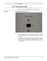


A3 Installation
UltraScan Use
r
’s Guide Reference Series Rev 1.0
XII
•
Connect tubes 2 and 3 to tube 5 and 6 respectively through their quick-
disconnect fittings.
•
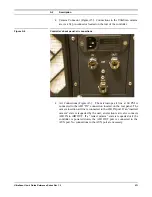
Connect the male quick-disconnect fitting of tube 1 to the outlet on the
backside of the controller labeled
Air Out
(Figure A6).
•
Snap the male quick-disconnect fitting of tube 4 into the inlet on the
backside of the controller labeled
Air In
(Figure A6).
The quick disconnect fittings automatically seal the lines off when not
connected to anything, so that they may be connected and disconnected from
the controller or the microscope without affecting the operation of the
microscope.
A3.2 Mounting the camera
If you are mounting the camera to the microscope:
•
Vent the microscope’s viewing chamber following the microscope
manufacturer’s instructions.
•
Remove the blanking flange on the microscope’s on-axis camera port
beneath the film chamber. Follow the instructions given by the
microscope manufacturer.
•
Inspect the o-ring seal to the microscope for dust and fibers.
The seal must be clean in order to maintain the vacuum. If necessary, clean
and lightly coat the o-ring with vacuum grease.
•
Mount the camera to the microscope.
Make sure that the sealing surfaces are clean.
•
Reverse the end-point connections for tubes 1 and 3 from the normal
configuration shown in figure A9.
Plug tube 3 into the
Air Out
outlet on the backside of the controller
(Figure A6) and plug tube 1 into tube 6 (pressure-regulator line). This is a
reversal of the normal configuration but will ensure that when the diffusion
pump gate valve is closed during the rough pump-down, the camera will be
in the inserted, open position.
•
Start the evacuation of the viewing chamber.
Follow the instructions given by the manufacturer.
•
When the pump-down cycle is complete, restore the configuration of
the pressure lines to the normal configuration as shown in figure A9.
Plug tube 1 into
Air Out
on the backside of the controller and tube 3 into
tube 6.
Содержание UltraScan 894
Страница 21: ...Magnification Calibration UltraScan User s Guide Reference Series Rev 1 0 2 13 Figure 2 15 Calibration window...
Страница 30: ...Image Saving and Printing UltraScan User s Guide Reference Series Rev 1 0 3 9 Figure 3 10 Control palette...
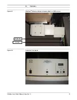
Страница 46: ...A2 Description UltraScan User s Guide Reference Series Rev 1 0 VIII Figure A 7 Controller s back panel...
Страница 55: ...UltraScan User s Guide Reference Series Rev 1 0 XVII Appendix 2 CE certification...


