


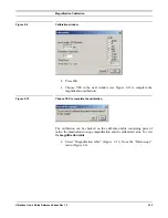


Magnification Calibration
UltraScan Use
r
’s Guide Reference Series Rev 1.0
2-11
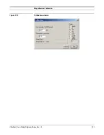
Figure 2-11
Magnification table
The first column represents the nominal TEM magnification and the second
column is the actual magnification at the CCD.
2.6.2 “High” magnification
•
Record a lattice image of the crystalline sample (Figure 2-12).
Figure 2-12
High-resolution image of a crystalline sample
•
Choose “Calibrate image from Diffractogram…” under the
“Microscope” menu (Figure 2-6)
.
Содержание UltraScan 894
Страница 21: ...Magnification Calibration UltraScan User s Guide Reference Series Rev 1 0 2 13 Figure 2 15 Calibration window...
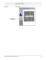
Страница 30: ...Image Saving and Printing UltraScan User s Guide Reference Series Rev 1 0 3 9 Figure 3 10 Control palette...
Страница 46: ...A2 Description UltraScan User s Guide Reference Series Rev 1 0 VIII Figure A 7 Controller s back panel...
Страница 55: ...UltraScan User s Guide Reference Series Rev 1 0 XVII Appendix 2 CE certification...


