GNS 430(A) Pilot’s Guide and Reference
190-00140-00 Rev. P
12-31
SECTION 12
ADDITIONAL FEATURES
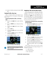
Entering an identifier:
1) Select the Data Link Page. Highlight ‘TEXTUAL
METAR’ and press the
ENT
Key.
2) Turn the small
right
knob and scroll through
the list of four letter identifiers.
3) Highlight the desired identifier and press the
ENT
Key.
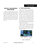
4) The text box displays the METAR data for the
selected identifier.
5) To request an updated graphic or textual
METAR for this airport, press the
MENU
key
to access the page menu and select ‘Request
METAR?’.
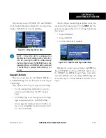
6) The METAR Request Page is displayed. The
request option is displayed on the Textual
METAR Page.
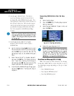
Displaying Wind Data
Displaying wind data on the NAV Weather
Page:
1) Select the NAV Weather Page.
2) Press the small
right
knob. The upper left hand
corner field flashes.
3) Turn the small
right
knob and select
‘WINDS’.
4) Press the small
right
knob. The wind icons are
displayed on the NAV Weather Page.
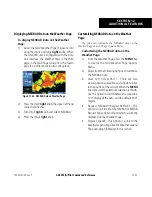
Displaying Temperature/Dewpoints
Temperature/Dewpoints are displayed on the NAV
Weather Page.
Displaying Temperature/Dewpoints on the
NAV Weather Page:
1) Select the NAV Weather Page.
2) Press the small
right
knob. The upper left hand
corner data field flashes.
3) Turn the small
right
knob and select ‘TEMP/
DP’.
4) Press the small
right
knob. The Temperature/
Dewpoints are displayed on the NAV Weather
Page.
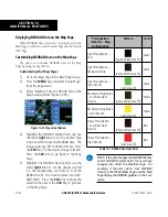
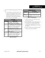
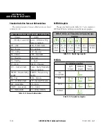
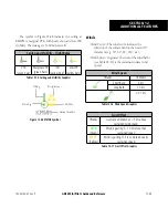
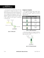
NOTE: See a complete description of all METAR,
Wind, and Temp-Dewpoint symbols at the end
of this section.
Troubleshooting
Although it is the responsibility of the facility that
installed the GDL 49 or GDL 69/69A to correct any
hardware problems, the pilot can perform some quick
troubleshooting steps to find the possible cause of a
failure.
First, ensure that the owner/operator of the aircraft
in which the GDL 49 or GDL 69/69A is installed has
subscribed to Echo Flight or XM Satellite Radio for a
Service Plan, and verify that it has been activated. Perform
a quick check of the circuit breakers to ensure the GDL 49
or GDL 69/69A has power applied. If a failure still exists,
continue to the Data Link Status Page.
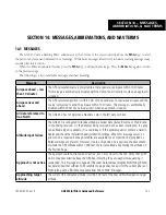
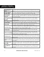
The fields on the Data Link Status Page may provide
insight to a possible failure. Information displayed at this
page should be noted and provided to the repair station.
The Connectivity Message table should also provide a
clear indication of any potential internal failures. If no
indications exist, check the circuit breakers and electrical
connections to the GDL 49 or GDL 69/69A, and ensure
the unit has power applied. Repair stations are equipped
to repair the system, should a hardware failure exist.
Содержание GNS 430
Страница 1: ...GNS 430 A Pilot s Guide and Reference ...
Страница 2: ......
Страница 28: ...GNS 430 A Pilot s Guide and Reference 190 00140 00 Rev P 1 20 SECTION 1 INTRODUCTION Blank Page ...
Страница 82: ...GNS 430 A Pilot s Guide and Reference 190 00140 00 Rev P 5 16 SECTION 5 FLIGHT PLANS Blank Page ...
Страница 116: ...GNS 430 A Pilot s Guide and Reference 190 00140 00 Rev P SECTION 6 PROCEDURES 6 34 Blank Page ...
Страница 250: ...GNS 430 A Pilot s Guide and Reference 190 00140 00 Rev P SECTION 14 MESSAGES ABBREVIATIONS NAV TERMS 14 14 Blank Page ...
Страница 254: ...GNS 430 A Pilot s Guide and Reference 190 00140 00 Rev P APPENDIX B SPECIFICATIONS B 2 Blank Page ...
Страница 265: ......

