background image


FLIGHT MANUAL STEMME S12


PAGE: 0-6 

DOCUMENT NUMBER 

REVISION: -- 

L400-912816 ISSUE FEBRUARY 21 2020 

DATE: --- --, ---- 

0.3


Contents 


0.1 

R

ECORD OF 

R

EVISIONS

 ...................................................................................... 0-3 

0.2 

L

IST OF 

E

FFECTIVE 

P

AGES

 .................................................................................... 0-4 

0.3 

C

ONTENTS

 ........................................................................................................ 0-6 

1. 

GENERAL ......................................................................................................... 1-1 

1.3 

A

BBREVATIONS

.................................................................................................. 1-3 
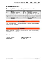
2. 

OPERATING LIMITATIONS ............................................................................... 2-1 
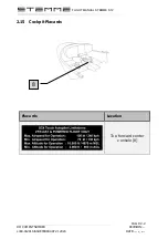
2.15 

C

OCKPIT 

P

LACARDS

 .......................................................................................... 2-2 

3. 

EMERGENCY PROCEDURES ............................................................................ 3-1 

3.9 

O

THER 

E

MERGENCIES

 ........................................................................................ 3-1 

3.9.4 

System Malfunctions .................................................................................... 3-1 

4. 

NORMAL OPERATING PROCEDURES ............................................................. 4-1 

4.1 

I

NTRODUCTION

 .................................................................................................. 4-1 

4.1.1 

Primary Flight Display ................................................................................... 4-4 

4.1.2 

GPS-Map ..................................................................................................... 4-13 

4.1.3 

Engine Indicating System .......................................................................... 4-15 

4.1.4 

Autopilot ..................................................................................................... 4-16 

4.1.5 

Autopilot Modes ........................................................................................ 4-22 

4.4 

A

UTOPILOT 

P

RE

-

FLIGHT 

I

NSPECTIONS

 .................................................................. 4-25 

4.5 

N

ORMAL 

O

PERATIONS 

P

ROCEDURES AND 

R

ECOMMENDED 

A

IRSPEEDS

 ................. 4-26 

4.5.1 

Engine Start, Warm-up and Taxi Procedures .......................................... 4-26 

4.5.3 

Cruise and Cross-country Flying ............................................................... 4-29 

5. 

FLIGHT PERFORMANCE ................................................................................... 5-1 

6. 

MASS AND BALANCE ..................................................................................... 6-1 

6.5 

E

QUIPMENT 

L

IST

 ................................................................................................. 6-1 

7. 

SYSTEM DESCRIPTION OF THE S12 AND ITS EQUIPMENT ............................... 7-1 

7.1 

G

ENERAL 

D

ESCRIPTION

 ...................................................................................... 7-1 

7.1.1 

Line Replaceable Units ................................................................................ 7-1 

7.1.2 

System Architecture .................................................................................... 7-5 

7.1.3 

Dependency of AHRS data ........................................................................ 7-6 

7.1.4 

Restrictions .................................................................................................... 7-7 

7.2 

O

PERATION

 ...................................................................................................... 7-8 

7.2.1 

General Operation ...................................................................................... 7-8 

7.2.2 

PFD Operation and Control ...................................................................... 7-13 

7.2.3 

Engine Indicating System Display ............................................................ 7-13 

7.2.4 

G3X Autopilot ............................................................................................. 7-13 

7.3 

Instrument Panel ........................................................................................ 7-15 

8. 

HANDLING, MAINTENANCE AND SERVICING .............................................. 8-1 


Содержание G3X Touch

Страница 1: ......

Страница 2: ...ions contained in the associated Aircraft Flight Manual and this Supplement CONTACT STEMME AG Flugplatzstrasse F2 Nr 6 7 D 15344 Strausberg Phone 49 3341 3612 0 E mail info stemme com Web www stemme c...

Страница 3: ...OA EASA 21J 250 In the table hereafter only the latest approved revision must be countersigned New or corrected text sections of the revised page s will be marked by a vertical line on the outer side...

Страница 4: ...7 X Feb 21 2020 3 8 X Feb 21 2020 3 9 X Feb 21 2020 3 10 X Feb 21 2020 Section 4 4 1 X Feb 21 2020 4 2 X Feb 21 2020 4 3 X Feb 21 2020 4 4 X Feb 21 2020 4 5 X Feb 21 2020 PAGE APPR Rev No Date 4 6 X F...

Страница 5: ...6 6 1 Feb 21 2020 6 2 Feb 21 2020 Section 7 7 1 Feb 21 2020 7 2 Feb 21 2020 7 3 Feb 21 2020 7 4 Feb 21 2020 7 5 Feb 21 2020 7 6 Feb 21 2020 7 7 Feb 21 2020 7 8 Feb 21 2020 7 9 Feb 21 2020 7 10 Feb 21...

Страница 6: ...16 4 1 5 Autopilot Modes 4 22 4 4 AUTOPILOT PRE FLIGHT INSPECTIONS 4 25 4 5 NORMAL OPERATIONS PROCEDURES AND RECOMMENDED AIRSPEEDS 4 26 4 5 1 Engine Start Warm up and Taxi Procedures 4 26 4 5 3 Cruise...

Страница 7: ...reen mode engine data voltmeter and ammeter and fuel management information Each MFD can be operated in individual split modes where more than the initial function is displayed The G3X system is also...

Страница 8: ...mma to separate the thousands digit For example 2 000 ft 2 000 ft NOTICE The Garmin G3X System is approved as an additional supporting instrument Refer to the non electric flight instruments for prima...

Страница 9: ...S Engine Indicating System GPS Global Positioning System HSI Horizontal Situation Indicator IAS Indicated Airspeed IMC Instrument Metrological Condition LMFD Left Multifunction Display LRU Line Replac...

Страница 10: ...FLIGHT MANUAL STEMME S12 PAGE 1 4 DOCUMENT NUMBER REVISION L400 912816 ISSUE FEBRUARY 21 2020 DATE THIS PAGE IS INTENTIONALLY LEFT BLANK...

Страница 11: ...130 kt Maximum approved speed for safe use of the autopilot VAP Minimum speed for operation of the autopilot 130 kph 70 kt Minimum approved speed for safe use of the autopilot WARNING The autopilot s...

Страница 12: ...FLIGHT MANUAL STEMME S12 PAGE 2 2 DOCUMENT NUMBER REVISION L400 912816 ISSUE FEBRUARY 21 2020 DATE 2 15 Cockpit Placards Placards Location Top forward center console 8 8...

Страница 13: ...9 4 1 Fuel Pressure The fuel pressure indicator features a bar graph display Garmin G3X System indications are set to the permissible BRP ROTAX fuel pressure values Low fuel pressure 0 15 bar Normal f...

Страница 14: ...should be operational within one minute of power up If any instrument remains flagged the G3X Touch should be serviced Crew Alerting System CAS System malfunctions will also be announced by the Crew...

Страница 15: ...ation Indicator HSI Touch on an active CAS message to acknowledge it CAS Annunciation includes exceedance of engine parameters monitored by the GARMIN Engine Indication System EIS Indication of Unusua...

Страница 16: ...access a message Touch Messages at the bottom of the screen to view messages Touch Messages again to remove the messages GPS Status Indication The GPS status icon is located on the in left half of th...

Страница 17: ...N L400 912816 ISSUE FEBRUARY 21 2020 DATE A red X will be displayed over the aircraft icon on the map page A red X will be displayed over the whole terrain page Engine Parameters A red flashing engine...

Страница 18: ...dicated in black letters in red boxes in the autopilot status box Reversionary Mode In the event of a display failure the G3X Touch System automatically switches to reversionary backup mode In reversi...

Страница 19: ...splay In the case of loss of the RMFD the LMFD switches to reversionary mode and displays the engine data and the PFD in split screen mode If the engine data are not displayed on the LMFD proceed acco...

Страница 20: ...PFD screen DISENGAGE autopilot if controls are still jammed LMFD and RMFD Turn PFD and MFD unit switch OFF if controls are still jammed PFD circuit breaker PULL Slip clutch OVERPOWER actuator by hand...

Страница 21: ...s indicated by The magenta colored GPS status information in the HSI will disappear and GPS related data magenta will not be available A red X will be displayed over the aircraft icon on the map page...

Страница 22: ...FLIGHT MANUAL STEMME S12 PAGE 3 10 DOCUMENT NUMBER REVISION L400 912816 ISSUE FEBRUARY 21 2020 DATE THIS PAGE IS INTENTIONALLY LEFT BLANK...

Страница 23: ...rer documentation Garmin G3X Touch Pilot s Guide P N 190 01754 00 4 1 Introduction General operation The G3X system is controlled by pushbuttons and rotary knobs located on the main displays as well a...

Страница 24: ...RMFD set main system master switch ON set PFD switch ON set MFD switch ON set engine system master switch ON Push nose cone handle to OPEN and LOCKED position NOTICE During system initialization the A...

Страница 25: ...FLIGHT MANUAL STEMME S12 PAGE 4 3 DOCUMENT NUMBER REVISION L400 912816 ISSUEFEBRUARY 21 2020 DATE THIS PAGE IS INTENTIONALLY LEFT BLANK...

Страница 26: ...BRUARY 21 2020 DATE 4 1 1 Primary Flight Display The Primary Flight Display screen features a horizon airspeed attitude altitude vertical speed heading and course deviation information The following f...

Страница 27: ...ng Bug 6 Flight Director Command Bars 22 CDI Scale 7 Aircraft Symbol 23 Selected Course 8 Slip Skid Indicator 24 Altimeter Barometric Setting 9 Lateral Deviation Scale Course Deviation 25 Altimeter 10...

Страница 28: ...actual airspeed is displayed inside the black pointer The pointer remains black until reaching never exceed speed VNE at which point it turns red A color coded speed range strip is located on the movi...

Страница 29: ...c labels and major tick marks are shown at intervals of 100 feet Minor tick marks are at intervals of 20 feet The current altitude is displayed in the black pointer The Selected Altitude is displayed...

Страница 30: ...ents or Touch the Selected Altitude Enter the desired altitude using the keypad and touch Enter Syncing to the current altitude Touch the Selected Altitude Touch Set to Current and touch Enter Syncing...

Страница 31: ...e pitch scale Pitch markings occur at 2 5 intervals through all pitch ranges The inverted white triangle indicates zero on the roll scale Major tick marks at 30 and 60 and minor tick marks at 10 20 an...

Страница 32: ...eading up orientation at the bottom of the page Letters indicate the cardinal points and numeric labels occur every 30 Major tick marks are at 10 intervals and minor tick marks at 5 intervals The curr...

Страница 33: ...heading on the PFD screen Touch Set to Current and touch Enter No Function No Function 1 Course Deviation To From Indicator 7 Rotating Compass Rose 2 Selected Heading 8 Selected Heading Bug 3 Current...

Страница 34: ...A magenta Turn Rate Trend Vector shows the current turn rate The end of the trend vector gives the heading predicted in 6 seconds based on the present turn rate A standard rate turn is shown on the in...

Страница 35: ...ssing the corresponding hardkeys 4 1 2 1 Direct To Navigation using the G3X Touch The Direct to method of navigation initiated by pressing the Direct to Key is quicker to use than a flight plan when t...

Страница 36: ...ct to Window is displayed Touch the waypoint identifier Touch Find Touch the Recent Tab or Touch the Nearest Airports Tab or Touch the Flight Plan Tab or Touch the User Tab Touch the desired waypoint...

Страница 37: ...nt Information about RPM Oil Pressure and Oil Temperature is permanently displayed on the left side of the EIS Other information is available through three soft key tabs Press Main to display informat...

Страница 38: ...ce This is a page available on the PFD screen To access the G3X autopilot interface touch the autopilot status box The interface offers the following controls NOTICE The following functions of the aut...

Страница 39: ...d not supported LVL Engages the autopilot if the autopilot is disengaged in level vertical and lateral modes HDG Selects deselects heading mode NAV Selects deselects navigation mode APPR Selects desel...

Страница 40: ...E 4 18 DOCUMENT NUMBER REVISION L400 912816 ISSUEFEBRUARY 21 2020 DATE 4 1 4 1 Autopilot Status Indicators The autopilot status indicator is always displayed in the autopilot status box at the upper c...

Страница 41: ...control PIT ALT VS IAS LVL VNAV ALTS ALTV In the right part of the autopilot status box indicates an active vertical autopilot mode No symbol indicates that no vertical autopilot mode is active An act...

Страница 42: ...ot status box on the PFD screen to open the autopilot control panel Press the AP Softkey to disengage the autopilot or Press the disengage pushbutton NOTICE When the autopilot is not active the AP dis...

Страница 43: ...4 1 4 3 Flight Director Operation The flight director function provides pitch and roll commands to the pilot and autopilot which are displayed on the PFD screen With only the flight director active th...

Страница 44: ...ctor in selected mode 4 1 5 Autopilot Modes For more detailed description refer to the manufacturers documentation Garmin G3X Touch Pilot s Guide Doc No 190 01754 00 4 1 5 1 Level Mode LVL Level mode...

Страница 45: ...Mode Description Control Annun ciation Reference Change Increment Pitch Hold Holds the current aircraft pitch attitude may be used to climb descent tot he selected altitude Default PIT 0 5 Selected Al...

Страница 46: ...V Softkey VNAV VNV Target Altitude Capture Captures the Vertical Navigation VNV Target Altitude Armed when VNAV is selected ALTV The mode reference is displayed next to the active mode annunciation fo...

Страница 47: ...id magnetometer data within 2 minutes after PFD startup Check GPS reception Select info page on PFD screen Verify valid GPS data Check AP mode indication Touch autopilot status box then touch AP Verif...

Страница 48: ...ON Nosecone handle OPEN and LOCKED TCU performs self test main fuel pump cycles red battery charge control light ON CAUTION When the TCU is energized master switch ON and nosecone OPEN and LOCKED the...

Страница 49: ...three seconds The time delay allows the propeller blades to be fully deployed before the engine starts and consequently reduces the loads for the propeller blades and their corresponding stops In case...

Страница 50: ...le slightly add up to 10 power to improve the engine start up behavior Engine RPM SET approx 2000 RPM Oil pressure GREEN arc after 10 seconds WARNING If the minimum oil pressure is not indicated withi...

Страница 51: ...topilot status box then touch ALT refer to 4 1 5 3 Vertical Mode Autopilot horizontal mode setting Set HDG or GPS depending of the chosen mode CAUTION Cross check attitude altitude and speed regularly...

Страница 52: ...e autopilot WARNING All announcements displayed on the PFD screen must be accomplished promptly otherwise the aircraft may attain flight situations where the pilot must immediately take over manually...

Страница 53: ...ilot must be deactivated In order to save battery power the pilot may elect to shut down the display units while soaring To deactivate the AP execute the following procedure Quick disengage Push butto...

Страница 54: ...us light ON Choke ON for cold engine Throttle IDLE max 10 Ignition START for a minimum of three seconds WARNING If OAT is extremely low i e at high altitudes or in cold areas battery capacity after lo...

Страница 55: ...e the following checks must be performed before the next flight in accordance with the aircraft maintenance manual AMM section 5 3 13 item 5 for the retarder module and AMM section 5 3 15 items 3 thro...

Страница 56: ...d within 10 seconds stop engine immediately NOTICE Minimum oil pressure 22 psi 1 5 bar with cold engine at low RPM up to 102 psi 7 0 bar are normal Fuel selector switch Fuel management as required rig...

Страница 57: ...OCUMENT NUMBER REVISION L400 912816 ISSUEFEBRUARY 21 2020 DATE CAUTION During engine warm up oil temperature and CHT must be monitored continuously In case of a malfunction of the cowl flaps a danger...

Страница 58: ...FLIGHT MANUAL STEMME S12 PAGE 4 36 DOCUMENT NUMBER REVISION L400 912816 ISSUEFEBRUARY 21 2020 DATE THIS PAGE IS INTENTIONALLY LEFT BLANK...

Страница 59: ...FLIGHT MANUAL STEMME S12 PAGE 5 1 DOCUMENT NUMBER REVISION L400 912816 ISSUEFEBRUARY 21 2020 DATE 5 Flight Performance No change to basic flight manual...

Страница 60: ...FLIGHT MANUAL STEMME S12 PAGE 5 2 DOCUMENT NUMBER REVISION L400 912816 ISSUEFEBRUARY 21 2020 DATE THIS PAGE IS INTENTIONALLY LEFT BLANK...

Страница 61: ...GARMIN G3X System can be only installed during the manufacturing of the aircraft The system weight is considered in the Weight Balance Report for the initial Conformity Inspection 6 5 Equipment List...

Страница 62: ...FLIGHT MANUAL STEMME S12 PAGE 6 2 DOCUMENT NUMBER REVISION L400 912816 ISSUEFEBRUARY 21 2020 DATE THIS PAGE IS INTENTIONALLY LEFT BLANK...

Страница 63: ...X Touch Pilot s Guide Doc No 190 01754 00 7 1 General Description 7 1 1 Line Replaceable Units The G3X Touch system may consist of the following Line Replaceable Units LRUs Display Unit GDU 450 or 455...

Страница 64: ...gine and airframe sensors Air Data Computer Sensor Unit GSU 25 Air Data Computer Processes data from the pitot static system and outside air temperature Attitude and Heading Reference System AHRS Prov...

Страница 65: ...21 2020 DATE Magnetometer GMU 11 Magnetometer Provides magnetic heading information Temperature Probe GTP 59 Temperature Probe Provides raw air temperature data GPS Controller GPS 20A GPS Controller P...

Страница 66: ...STEMME S12 PAGE 7 4 DOCUMENT NUMBER REVISION L400 912816 ISSUEFEBRUARY 21 2020 DATE Autopilot Servo GSA 28 Two autopilot servos GSA 28 are installed in the aircraft Provides automatic control of pitch...

Страница 67: ...ic system of the aircraft this minimum configuration provides airspeed altitude attitude heading and navigation information to the pilot This system is completed by an analog to digital converter GEA2...

Страница 68: ...the AHRS receives appropriate combinations of information from the external sensor inputs The AHRS GSU 25 corrects for shifts and variations in the Earth s magnetic field by applying the Magnetic Fie...

Страница 69: ...ipment External GPS or Navigation equipment works independently and is not connected with the G3X equipment The ATC equipment works independently from the G3X but receives position data for ADS B func...

Страница 70: ...e for viewing the nearest airports intersections NDBs VORs waypoints frequencies and airspaces Direct To Key Press to activate the Direct To function enter a destination waypoint and establish a direc...

Страница 71: ...this case if the desired identifier appears touch Enter to confirm the entry without entering the rest of the identifier manually This can save the pilot from having to enter all the characters of th...

Страница 72: ...ob associated with the MFD The Nearest Pages are selected by pressing the NRST Key To select the NRST pages Touch the NRST Softkey Touch the Page Navigation Bar Touch the desired page from the Select...

Страница 73: ...when you are receiving DGPS corrections in 3D mode Lost Satellite Reception the receiver is no longer tracking enough satellites for a 2D or 3D fix To view GPS receiver status information Turn the la...

Страница 74: ...llowing databases are available with the G3X Touch depending on the unit Americas Atlantic or Pacific See the Additional Feature section for information on Airport Directories FliteCharts and SafeTaxi...

Страница 75: ...ifferent tabs on the Eng Page on the multi function display MFD Left right cylinder head temperature Oil temperature pressure Fuel pressure Voltage current of main and engine battery Left right wing f...

Страница 76: ...n GPS horizontal mode requires GPS data Altitude hold ALT vertical mode Vertical speed VS vertical mode Vertical navigation VNAV vertical mode The autopilot interface is part of the electronic flight...

Страница 77: ...WARNING This AP has a wide range of capabilities that are not covered in the Aircraft Flight Manual supplement AFMS Capabilities that are not described here are not approved for use 7 3 Instrument Pa...

Страница 78: ...FLIGHT MANUAL STEMME S12 PAGE 7 16 DOCUMENT NUMBER REVISION L400 912816 ISSUEFEBRUARY 21 2020 DATE THIS PAGE IS INTENTIONALLY LEFT BLANK...

Страница 79: ...FLIGHT MANUAL STEMME S12 PAGE 8 1 DOCUMENT NUMBER REVISION L400 912816 ISSUEFEBRUARY 21 2020 DATE 8 Handling Maintenance and Servicing Refer to operator s manual of Garmin G3X system latest revision...

Страница 80: ...FLIGHT MANUAL STEMME S12 PAGE 8 2 DOCUMENT NUMBER REVISION L400 912816 ISSUEFEBRUARY 21 2020 DATE THIS PAGE IS INTENTIONALLY LEFT BLANK...

Отзывы: