Page 24 | HEEGM Service Manual part# 4532502 (Rev 0)
6 COMPONENTS
(CONT.)
6.8 Electrode
All burners are equipped with continuous electronic spark electrodes to ensure flame is on at all
times during operation.
Continuous sparking
is intended to remain energized until its corresponding ignition control
module senses flame current. Electrical spark generation is then shut off until flame current is no
longer sensed. Refer to the wiring diagrams for proper ignition wire connections to the ignition
module.
Spark gap
: min 0.125”(1/8”), and max 0.160”(5/32”).
Visual inspection
is often sufficient to check for a faulty electrode. Check for bent, damaged
electrodes or cracked ceramics on the electrodes.
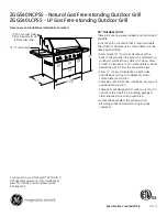
6.8.1 Removing & Installing an Electrode
WARNING
Disconnect electrical power from the unit.
i
IMPORTANT
You CANNOT loosen the electrodes from
the burner side. Remove the valve panel and the wire
channel cover to gain access to the electrodes.
i
IMPORTANT
If there are metal wire ties on the silicone
sleeve, ensure to keep the metal ties away from the
electrodes to avoid shorting. See illustration below.
To replace an electrode:
4
7
7
5
Screwdriver
Silicone Sleeve
5a
Some components are not shown.
Metal Wire Tie,
or Silicone Rubber Tape
1.
WARNING: Disconnect electrical power from the unit.
2. Remove the knobs and the valve panel (see “6.2 Valve Panel”).
3. Loosen the screws for the grease chute (at the bottom of the chute) and drop the grease chute
down.
4. Remove the screws at the front of the wire channel to take the cover off.
Содержание HEEGM48CL
Страница 34: ...Page 34 HEEGM Service Manual part 4532502 Rev 0 7 WIRING DIAGRAMS HEEGM24CL 120VAC ...
Страница 35: ...Page 35 HEEGM Service Manual part 4532502 Rev 0 7 WIRING DIAGRAMS CONT HEEGM24CL 240VAC ...
Страница 37: ...Page 37 HEEGM Service Manual part 4532502 Rev 0 7 WIRING DIAGRAMS CONT HEEGM36CL 240VAC ...
Страница 41: ...Page 41 HEEGM Service Manual part 4532502 Rev 0 7 WIRING DIAGRAMS CONT HEEGM60CL 240VAC ...
Страница 43: ......