background image

13–10–613 SP    Page 50

13. Install original oil return by slipping tube through

the fitting at the discharge manifold flange until
ferrule bottoms in the fitting.  If a new fitting and
return tube are used, slip the tube through the
fitting until it touches the bottom of the separator,
then raise the tube about 1/4 inch off the bottom
and tighten the fitting nut securely.  Connect the
other end of the tube to the compressor oil return
tube elbow.  Do not bend tube or raise tube further
than 1/4”–1/2” from the bottom of the separator.

14. Reconnect compressor oil return tube to tube

elbow.

COMPRESSOR OIL SYSTEM CHECK – The com-
pressor should be at operating temperature at the time
of the checks.  On–half hour of loaded operation is usu-
ally sufficient to reach level–out operating tempera-
tures.  The data shown below is for an oil–system in
good condition.

If the unit will operate at discharge temperatures over
200

_

 F for more than 4 consecutive hours, refer to the

“High Temperature Operation” paragraph and select a
lubricant for this service.  Regardless of level of
sustained discharge temperature, the high discharge
air temperature switch must never be set higher than
225

_

 F shutdown temperature.

Air and Oil Discharge Temperature – Check with a
thermometer in the tapped opening on top of the com-
pressor discharge pipe to the oil reservoir.

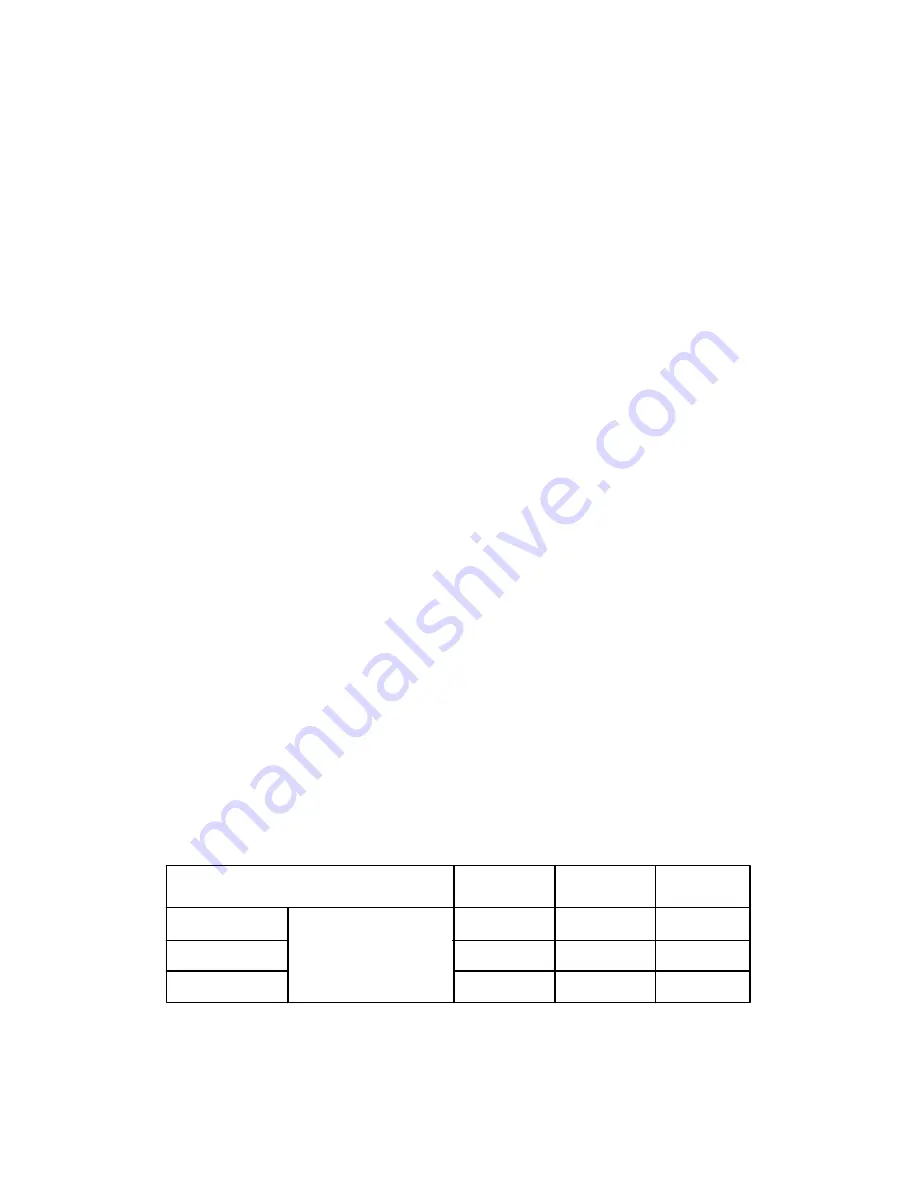
For  Air Cooled Oil Systems, FIGURE 5–10 shows
the normal upper limit of discharge temperatures for
varying ambient temperatures beginning at the system
design point of 80

_

 F. At ambient temperatures below

80

_

 F, the mixing valve will hold the discharge tempera-

ture at the 80

_

 F ambient temperature point.  Above

80

_

 F, the oil cooler is fully used and the discharge tem-

perature varies degree for degree with the ambient
temperature.

For Water Cooled Oil Systems, the water flows at var-
ious temperatures outlined in Section 2 will hold the dis-
charge temperature below the 80

_

 F ambient tempera-

ture level of FIGURE 5–10.  Small variations in specific
water flows or temperatures will not be noted in the dis-
charge temperature since the water control valve will
tend to hold a constant oil temperature.  A significant
change in the discharge temperature is cause to check
for a change in water flow or temperature.

Oil Inlet Pressure – Check at the fitting in the line near
the compressor oil inlet.  With air receiver pressure at
100 psi, oil inlet pressure should be 75–85 psig.

Oil Cooler Oil Pressure Differential (Air–Cooled
Radiator)
 – 2 to 25 psi (65 to 150 PSIG Receiver Pres-
sure) – Check at the fitting in the inlet and outlet lines
of the oil cooler.

Oil Cooler Oil Pressure Differential (Water–Cooled
Heat Exchanger)
 – 2 to 25 PSI (65 to 150 PSIG Re-
ceiver Pressure) – Check at the heat exchanger oil inlet
and outlet fittings.

Oil Cooler Temperature Differential (Air–Cooled
Radiator)
 – The oil temperature differential depends
on the temperature of the air at the oil cooler fan and
cleanliness of core faces.  As ambient temperatures
and core restrictions increase, the oil cooler outlet tem-
perature will increase. The inlet oil temperature may be
checked at the fittings in the oil inlet line on the oil cooler
module.  The outlet oil temperature may be checked at
the fitting in the oil outlet line.

Oil Cooler Temperature Differential (Water–Cooled
Heat Exchanger)
 – The oil temperature differential de-
pends on the inlet water temperature and the water flow
rate permitted by the water flow control valve setting.
The oil inlet temperature is approximately the same as
the air discharge temperature – see the gauge on the
instrument panel.  The oil outlet temperature may be
checked at the compressor oil inlet line fitting.

Oil Cooler Water Pressure Differential (Water–
Cooled Heat Exchanger)
 – The water pressure differ-
ential through the heat exchanger will depend on the
supply pressure, flow rate, cooler tube cleanliness and
outlet pressure.  The inlet and outlet water pressure
may be checked at the pipe fittings supplied by the
customer.

FIGURE 5–10  –  AMBIENT TEMPERATURES

         Ambient Temperature (

_

F.)

80

90

100

   350 HP

 Discharge

171

181

191

   400 HP

 Temperature

175

185

195

   500 HP

_

 F

184

194

204*

*   For temperatures above 200 F see “High Temperature Operation”.

Содержание ELECTRA-SAVER EAYQ E

Страница 1: ...GARDNER DENVER ELECTRA SAVER STATIONARY BASE MOUNTED COMPRESSOR WITH OPTIONAL ES CONTROLLER MODELS EAYQ_E EAYS_E OPERATING AND SERVICE MANUAL 13 10 613 SP 2nd Edition December 1995 ...

Страница 2: ...enver Air Compressor distributor refer to the yellow pages of your phone directory or contact Distribution Center Factory Gardner Denver Machinery Inc Gardner Denver Machinery Inc Master Distribution Center 1800 Gardner Expressway 5585 East Shelby Drive Quincy IL 62301 Memphis TN 38141 Phone 217 222 5400 Phone 901 542 6100 Fax 217 223 5897 800 245 4946 Fax 901 542 6159 REMANUFACTURED AIR ENDS When...

Страница 3: ...hazard which will cause severe personal injury death or substantial property damage if the warning is ignored Warning is used to indicate the presence of a hazard which can cause severe person al injury death or substantial property damage if the warning is ignored Caution is used to indicate the presence of a hazard which will or can cause minor personal injury or property damage if the warning i...

Страница 4: ...parts specify Compressor MODEL Method of Cooling HORSEPOWER and SERIAL NUMBER see nameplate on unit The Serial Number is also stamped on top of the cylinder flange to the right of the inlet housing All orders for Parts should be placed with the nearest authorized distributor Where NOT specified quantity of parts required per compressor or unit is one 1 where more than one is required per unit quan...

Страница 5: ...and Draining Oil System 43 Cold Ambient Operation 42 Cold Weather Operation 12 Cold Weather Operation Installation for 12 Compression Principle 1 Compressor 1 Compressor Capacity Control Turn Valve Units Only 35 Compressor Oil Cooler 45 Compressor Oil Filter 44 Compressor Oil Separator 48 Compressor Oil System 40 Compressor Oil System Check 50 Configuration Adjustments 24 Connection Failure 21 Con...

Страница 6: ...Line Inlet 12 Location 8 Low Demand Mode Operation 19 Low Oil Pressure Shutdown 21 Lubricant Recommended 40 Lubricant Change Procedure 41 Lubrication Cooling and Sealing 1 Lubrication Motor 15 LUBRICATION OIL COOLER OIL FILTER SEPARATOR SECTION 5 40 Main Adjustments Menu Controller 21 Main Starter 35 Maintenance Adjustments 23 MAINTENANCE SCHEDULE SECTION 8 54 Minimum Discharge Pressure Valve 31 M...

Страница 7: ...ctions iii Reservoir Oil 48 Reservoir Pressure Transducer 34 Safety Precautions 4 5 Schematics Control 35 Sealing Lubrication and Cleaning 1 Separator Compressor Oil 48 Separator Differential Pressure Shutdown 21 Separator Trap Moisture 12 Sequence Adjustments 24 Sequence Mode Operation 19 Sequenced System Checkout 29 Sequencing Compressors Compressor System 27 Establishing Initial Sequence 28 Gen...

Страница 8: ...Discharge 34 System 34 Transducer Reservoir Pressure 34 System Pressure 34 Transformer Control 34 TROUBLE SHOOTING SECTION 9 55 TROUBLE SHOOTING CONTROLS SECTION 10 58 Trouble Shooting Controls Advisory Troubleshooting 59 Controls Troubleshooting 63 Display Modes 58 Shutdown Troubleshooting 60 Tube Inlet 52 Turn Valve 1 33 Turn Valve Actuator EAQ Units Only 33 Unit Setup Adjustments 25 Valve Blowd...

Страница 9: ...ure 4 3 Schematic Tubing Diagram 30 Figure 4 4 Blowdown Valve 31 Figure 4 5 Minimum Discharge Pressure Valve 32 Figure 4 6 Inlet Valve 32 Figure 4 7 Shuttle Valve 33 Figure 4 8 Turn Valve Control 33 Figure 4 9 Turn Valve Actuator 34 Figure 4 10 Control Schematic Compressor at Full Load 36 Figure 4 11 Control Schematic Compressor Fully Unloaded Constant Speed Mode 37 Figure 4 12 Control Schematic C...

Страница 10: ... rotor groove normal vol ume is reduced and pressure increases Oil is injected into the cylinder to remove the heat of compression and seal internal clearances Volume re duction and pressure increase continues until the air oil mixture trapped in the interlobe cavity by the rotors passes the discharge port and is released to the oil res ervoir C Each rotor cavity follows the same fill com press di...

Страница 11: ...e 2 FIGURE 1 2 VIEW OF WATER COOLED UNIT WITH AFTERCOOLER LESS ENCLOSURE COMPRESSOR MOTOR SIDE 208EAY797 Ref Drawing FIGURE 1 3 VIEW OF WATER COOLED UNIT WITH AFTERCOOLER LESS ENCLOSURE MOTOR END 208EAY797 Ref Drawing ...

Страница 12: ...FIGURE 1 4 VIEW OF WATER COOLED UNIT WITH AFTERCOOLER LESS ENCLOSURE COMPRESSOR RESERVOIR END 208EAY797 Ref Drawing FIGURE 1 5 VIEW OF WATER COOLED UNIT WITH AFTERCOOLER LESS ENCLOSURE RESERVOIR SIDE 208EAY797 Ref Drawing ...

Страница 13: ...er plug drain plugs covers the thermostat ic mixing valve or break any connections etc in the compressor air or oil sys tem until the unit is shut down and the air pressure has been relieved D Electrical shock can and may be fatal D Compressor unit must be grounded in accordance with the National Electrical Code A ground jumper equal to the size of the equipment ground conductor must be used to co...

Страница 14: ...ag and lockout be fore working on the unit this machine is automatically controlled and may start at any time D An Excess Flow Valve should be on all compressed air supply hoses ex ceeding 1 2 inch inside diameter OSHA Regulation Section 1926 302 D Do not exceed the rated maximum pressure values shown on the nameplate D Do not operate unit if safety devices are not operating properly Check peri od...

Страница 15: ...13 10 613 SP Page 6 DECALS 206EAQ077 212EAQ077 218EAQ077 211EAQ077 207EAQ077 ...

Страница 16: ...13 10 613 SP Page 7 DECALS 216EAQ077 217EAQ077 222EAQ077 221EAQ077 208EAQ077 ...

Страница 17: ...d area with ample space all around for maintenance Select a location that provides a cool clean dry source of air In some cases it may be necessary to install the air filter at some distance from the compressor to obtain proper air sup ply The compressor unit require electric motor cooling air as well as air to the compressor inlet Proper ventilation MUST be provided FIGURE 2 2 hot air must be ex ...

Страница 18: ... or trough below the floor level and pump or bail the drained oil 3 Pump oil from the reservoir filler opening or drain to a container ACOUSTIC ENCLOSURE The Electra Saver unit is furnished with an acoustic enclosure over the compres sor only as standard equipment The enclosure re duces the normal operating sound of the unit to 90 DBA or below in free field conditions AIR COOLED OIL COOLER MODULE ...

Страница 19: ...ion included in numbers 3 through 6 above All remote piping should be of adequate size to insure a minimum pressure loss Number 4 above lists the minimum pipe size to be used Long runs of pipe and the use of valves and fittings require larger than the minimum pipe sizes in the system to keep the pressure loss low All pipe and fittings used in a remote oil cooler system should be galvanized or trea...

Страница 20: ...uate size provided with a relief valve of proper setting a pressure gauge and a means of draining conden sate AFTERCOOLER FIGURE 1 2 and FIGURE 1 5 pages 2 and 3 An aftercooler will provide control of moisture entering the shop air lines while reducing the normal low discharge temperature of about 180_ F at 100 PSIG discharge pressure to near inlet air tempera ture or cooling water temperature Air...

Страница 21: ...cify NEMA 4 enclosure for electrical devices Extreme Cold Weather Operation Down To 40_F 40_C In addition to the above the following should be provided 1 A temperature switch to control the fan should be provided for better starting and quicker warm up This switch can be provided from the factory and will delay fan start up until discharge temperature reaches approximately 150 160_ F 2 It will pro...

Страница 22: ...ith a mois ture and oil proof sealing lacquer The inlet line should be the full size of the inlet opening on the compressor If an extra long line is necessary the pipe size should be increased according to Inlet Line Length Chart FIGURE 2 6 page 12 Accessibility for inlet air filter servicing must be consid ered when relocating the filters from the unit to a remote location DISCHARGE SERVICE LINE ...

Страница 23: ...t in aftercooler is used the maximum allowable water flow through the aftercooler is 100 gallons per minute on all 350 500 HP units and the maximum water inlet pressure is 150 PSIG If another aftercooler is used consult the manufacturer for operating limits When an aftercooler is piped in series with the oil cooler the maximum allowable flow rate through the oil aftercooler system is the max imum ...

Страница 24: ... operated grease gun The amount and type of grease added is very im portant Only enough grease should be added to replace the grease used by the bearing Too much grease can be as harmful as insufficient grease The grease cavity should be filled 1 3 to 1 2 full 5 Leave the relief plug temporarily off Reconnect the unit and run for about 20 minutes to expel the excess grease 6 Stop the unit Replace ...

Страница 25: ... Failure to release pressure may result in personal injury or death During unloaded operation and after shutdown the system will partially drain back into the oil res ervoir and the oil level may read higher than when operating on load DO NOT DRAIN OIL TO COR RECT on the next loaded cycle or start oil will again fill the system and the gauge will indicate the operating level 2 Air Filter Inspect t...

Страница 26: ...T COLD OR HOT STARTING PROCEDURES Unit Cold If the unit is a water cooled heat exchang er model open any manual water inlet valves wide open Start the unit by pushing either the CONSTANT RUN button or one of the AUTO buttons Since the unit is equipped with a minimum 65 psig pressure dis charge valve no special procedure to maintain unit res ervoir pressure is required Unit Hot No warm up period is...

Страница 27: ...When the key is released the control will resume its normal operation as required An optional control may be wired into the Auto Sentry ES controller to interrupt and restart the unit based on controls by others When stopped by these controls the display indicates remote stop In any mode the compressor will start only if reservoir pressure is below 5 psig The display will indicate if the control i...

Страница 28: ... er is adjustable from 5 to 20 minutes Automatic Mode Operation This mode provides automatic start and timed stop and is best used in ap plications with long unloaded periods e g idle shifts or weekends and adequate storage to allow the com pressor to be stopped for periods of light demands Op eration during periods of moderate to heavy demands are identical to the low demand mode The automatic ti...

Страница 29: ...pressor Some of these are normal maintenance procedures and are intended to serve as a reminder to perform routine service Oth ers are conditions which can reduce the maximum compressor performance It will remain in effect until reset Check the display during routine inspections and perform maintenance as suggested Refer to the troubleshooting section for detailed information about each advisory T...

Страница 30: ...ibration phase relay low voltage relay and water press Amp Sensor Failure The optional current sensor used with the ES controller is used for operational tun ing and advisory purposes only The only shutdown functions are those when the controller senses improp er operation Connection Failure The ES controller checks input connectors and will shutdown if they become un plugged Other Shutdowns The c...

Страница 31: ...13 10 613 SP Page 22 FIGURE 4 2 FLOW CHART FOR SET UP PROGRAMMING ...

Страница 32: ...displayed The bottom line will indicate a time between 5 and 20 minutes It is factory set at 10 minutes This is the minimum time interval between blowdowns A longer blowdown time minimizes wasteful dumping of compressed air when loading is likely to occur in a short time 6 In the top line AUTO TIME is displayed The bottom line will indicate a time between 5 and 20 minutes It too is factory set at ...

Страница 33: ... dis played The bottom line will indicate a number of hours in the range of 1 to 5000 It is factory set at 24 This is the number of hours that this machine will stay in the role of lead compressor Normally it is desirable to set this to the same val ue on all sequenced units to equalize running hours Different values may be programmed if desired to help equalize hours 4 In the top line LAG START D...

Страница 34: ...or op eration It may be temporarily lowered to verify the function of the temperature shutdown system 4 FAN TYPE is displayed next on the top line Se lect AIR COOLED for units with package mounted air coolers only This will delay fan start up until the oil has warmed up in the package Select WATER COOLED for water cooled units or any unit with a remote cooler This will run the fan whenever the com...

Страница 35: ...onditions are outside of the compressor unit s design range Low operating voltage in particular can cause high amp draw This will heat the motor beyond its design and will normally trip the overload relay to prevent motor failure The ES however will automatically reduce the delivery to continue operation within design limits If severe conditions persist The controller will display HIGH MOTOR AMPS ...

Страница 36: ...r is at least one gallon for the rated CFM of a member com pressor in the system the largest if they differ If the system is operated load unload larger volume or wid er differential may be needed to prevent unnecessary starts or rapid compressor cycles Note that when de mand exceeds the capacity of the running unit s there will be a delay until the next unit starts and delivers additional air The...

Страница 37: ...eprived of air This is due to one of the outstanding features of the AUTO SENTRY ES sequencing system control is always executed locally by each member controller So while a controller or controllers is are counting down towards the final order they are also capable operating their compressor and will deliver air Once the se quence order is finally established setpoints will con tinue to be adjust...

Страница 38: ...t and another compressor s discharge These points will also vary from the actual system storage normally the air storage receiver The AUTO SENTRY ES sequencing system is de signed to tolerate minor variations The AUTO SENTRY ES sequencing system will automatically adjust the system setpoint to maintain the average sys tem pressure Overpressures within any member com pressor are prevented locally a...

Страница 39: ...QUENCE modes will occur when the pressure drops below the set pressure The remote is not capable of restarting following a SHUTDOWN The unit must be serviced and reset lo cally Alarm Relay The ES controller is provided with an alarm relay which may be connected to a remote mounted indicator light horn or into a PLC input of a plantwide control system The contact is commercial rated 2 amps at 120 v...

Страница 40: ... injury or machine damage Insure properly set valves are in stalled and maintained FIGURE 4 4 BLOWDOWN VALVE Blowdown Valve FIGURE 4 4 This valve normal ly is used for control functions but also serves to relieve reservoir pressure following a shutdown The blow down valve is a two way solenoid valve which is piped into the oil reservoir outlet ahead of the minimum pres sure valve When the solenoid...

Страница 41: ...or Inlet Valve FIGURE 1 4 page 3 and FIGURE 4 6 The Inlet valve restricts the inlet to control delivery and closes to unload the compressor At shutdown the inlet valve closes to prevent the back flow of air The inlet valve position is controlled by air pressure in its piston cylinder which is controlled by the Auto Sentry ES through solenoid valves IVC and IVO As Pressure to the piston is increase...

Страница 42: ...rn Valve Actuator Electra Saver only FIGURE 4 9 page 34 The turn valve actuator is a rotary rack and pinion device which positions the turn valve according to system demand Filtered oil from the compressor sump is directed to the outboard end of the two actuating cylinders to move the rack and ro tate the valve Located on the ends of the cylinders are adjusting screws which limit the travel of the...

Страница 43: ...uld be used for emergency purposes only use the keypad STOP RESET for normal con trolled stopping Automatic restarting or electrical shock can cause injury or death Open tag and lockout main discon nect and any other circuits before servicing the unit Vibration Switch The Auto Sentry ES controller has one additional input available for dealer or user installed optional shutdown switches The switch...

Страница 44: ...lly to provide low current starting For wye delta starters the motor nameplate amps must be first multi plied by 0 577 before using the heater table COMPRESSOR CAPACITY CONTROL TURN VALVE UNITS ONLY The capacity of the compressor is controlled by the ac tion of the Turn Valve and the Compressor Inlet Valve The turn valve controls compressor delivery to match demands of 40 to 100 of the compressor ...

Страница 45: ...13 10 613 SP Page 36 FIGURE 4 10 CONTROL SCHEMATIC COMPRESSOR AT FULL LOAD 204EAY797 Ref Drawing ...

Страница 46: ...13 10 613 SP Page 37 FIGURE 4 11 CONTROL SCHEMATIC COMPRESSOR FULLY UNLOADED CONSTANT SPEED MODE 205EAY797 Ref Drawing ...

Страница 47: ...13 10 613 SP Page 38 FIGURE 4 12 CONTROL SCHEMATIC COMPRESSOR FULLY UNLOADED LOW DEMAND MODE 206EAY797 Ref Drawing ...

Страница 48: ...13 10 613 SP Page 39 FIGURE 4 13 WIRING DIAGRAM 202EAY546 Ref Drawing ...

Страница 49: ...l cooler thermostatic mixing valve oil filter and into the compressor main oil gallery The oil passes through internal passages for lubrica tion cooling and sealing The air oil mixture is then discharged to the oil reservoir where a large part of the entrained oil drops out of the air stream the air then passes through the final oil separator where most of the remaining oil is removed The separate...

Страница 50: ...to run about five minutes at temperature or until temperature stabi lizes then shut down 3 Thoroughly drain the machine 4 Change to a new filter and separator 5 Fill the system with a full charge of the new lubri cant 6 Replace the drain plug before restoring power 7 Machine should then be run normally however total run time after the initial changeout should be 50 percent of normal anticipated se...

Страница 51: ...D to Capacity Capacity Centerline Size Initial Fill Refill of RUN 350 HP Air Cld 61 55 11 Water Cld 59 55 11 400 HP Air Cld 61 55 11 Water Cld 59 55 11 500 HP Air Cld 61 55 11 Water Cld 59 55 11 System capacity shown is for the initial fill of the compressor unit oil cooler module ONLY remotely mounted oil coolers will require additional oil to fill the piping between the com pressor unit and the ...

Страница 52: ...at high temperature during and after operation Always drain the complete system Draining when the oil is hot will help to prevent varnish deposits and carry away impurities To drain the system use one of the following methods 1 If the unit is not elevated high enough to use the oil reservoir drain line to drain oil a small hand electric or air operated pump should be used to drain reservoir throug...

Страница 53: ...is a vital part in maintaining a trouble free compressor since it re moves dirt and abrasives from the circulated oil The oil filter relief valve is located in the oil filter head The relief valve opens in the event the element becomes dirty enough to block the flow of oil Element must be replaced every 1000 hours or sooner or when top of the indicator on the filter is in the red CHANGE FILTER hal...

Страница 54: ...r nicks or cuts and replace if necessary Wipe tee handle 9 and O ring groove Then oil and replace O ring 10 insert tee handle 9 into head assembly 1 and replace snap ring 11 BEARING OIL FILTER An oil filter of the spin on type is used This filter is a vital part in maintaining a trouble free compressor since it removes dirt and abrasives from the circulated oil before it reaches the bearings The f...

Страница 55: ...es and must be installed on all remote elevated coolers per FIGURE 5 5 page 45 and the following instructions Remote mounted elevated coolers have a maximum pipe length of 30 feet each way and a maximum height of 20 feet with a minimum of fittings En gineering will review all remote ele vated cooler applications and recom mend pipe size on an individual basis Customer Service should include the en...

Страница 56: ...er vice pressure 65 to 150 psig with the unit warm a pressure drop of 3 to 15 psi can be expected between the oil inlet and the oil outlet Water pressure drop from water inlet to outlet will vary with the inlet pressure and amount of water flowing A normal pressure drop may range from 5 to 10 psi Any change in the pressure drop from that normally held may indicate tube leakage or fouling and shoul...

Страница 57: ... nut firmly with a wrench to reseat the packing around the valve stem then back off the nut until loose and finally retighten the nut finger tight Tightening the packing nut too tight may cause erratic operation An occasional drop of oil on the valve stem at the packing nut will prolong packing life If valve malfunctions check for bent or binding paint or corrosion on valve stem foreign material i...

Страница 58: ...er ential or sudden heavy oil carryover may indicate a ruptured element Inspection After removal of separator element shine a light inside the element to reveal areas of heavy dirt or varnish deposits or breaks ruptures in the ele ment media Removal Of Oil Separator For Inspection Or Re placement Air oil under pressure will cause severe personal injury or death Shut down compressor relieve system ...

Страница 59: ...fic water flows or temperatures will not be noted in the dis charge temperature since the water control valve will tend to hold a constant oil temperature A significant change in the discharge temperature is cause to check for a change in water flow or temperature Oil Inlet Pressure Check at the fitting in the line near the compressor oil inlet With air receiver pressure at 100 psi oil inlet press...

Страница 60: ... 140_F maximum for at least 15 minutes Swish the element around in the solution 2 minutes to help remove dirt Warm solution gives best results Rinse the element with a stream of water 40 PSI maximum opposite to normal air flow until rinse water is clear DRY THE ELE MENT THOROUGHLY BEFORE USING DO NOT USE LIGHT BULBS FOR DRYING Warm air 160_ F or less must be circulated as high surface tempera ture...

Страница 61: ... 150_ F Install the element in the filter body and fasten securely with the wing bolt Reinstall the dust cup and re taining band clamp Make sure the clamp is tight ened securely to prevent leakage Filter Element Life The element should be replaced after six 6 cleanings or if 1 Visual inspection indicates a rupture crack or pin hole in the pleated media Inspection should be done by placing a bright...

Страница 62: ...s on one coupling body and the flange on the opposite coupling body Tighten set screws in each coupling body b Insert individual cushions as shown in FIGURE 7 1 and slide the collar over the cushions and secure with cap screws Rein stall the cover plate FOR STYLE B COUPLING Rotating machinery can cause person al injury or death Do not operate unit with either the coupling guard or the collar remov...

Страница 63: ...mulation on oil aftercooler core faces and the cooling fan If cleaning is required clean the exterior fin surfaces of the cores by blowing compressed air carrying a nonflammable safety solvent in a direction opposite that of the cooling fan air flow This cleaning operation will keep the exterior cooling surfaces clean and en sure effective heat dissipation Every 1000 Hours Operation 1 Change the o...

Страница 64: ...tops after a short time Air Temperature this section page 56 2 High discharge 2 Replace switch temperature switch malfunction 3 Blown fuse in starter 3 Replace fuse control box investigate if fuses continue to blow 4 Motor starter overload 4 Reset and investigate heaters trip cause of overload Compressor does not 1 Improperly adjusted 1 Refer to Section 4 unload or load control and adjust control ...

Страница 65: ...cient cooling 3 Provide unrestricted supply air flow of cooling air 4 Clogged oil filter or 4 Replace filter or clean cooler interior cooler 5 Low compressor oil 5 Add oil to proper level Excessive Oil Consumption 1 Oil carryover through lines 1 See Oil Carryover below 2 Oil leaks at all fittings 2 Tighten or replace fittings and gaskets or gasket Oil Carry Over 1 Overfilling the reservoir 1 Drain...

Страница 66: ...um 6 Clean out or replace valve pressure valve causing low operating pressure 7 Operation at elevated 7 Reduce temperature See discharge temperatures High Discharge Air Temperature page 56 this section 8 Scavenge line check 8 Replace check valve valve failure 9 Water condensate in oil 9 Check oil reservoir tempera ture and if low change thermal mixing valve element to higher temperature Gardner De...

Страница 67: ...ining before a blowdown will be allowed AUTO TMR The time remaining of unloaded motor operation TOT HRS The total hours of compressor running LOAD HRS The hours of compressor delivery The following alternate displays may be called by pressing the or key MOTOR CURRENT The main motor current in amps Optional NEXT OIL CHANGE The estimated remaining time until the next recommended change NEXT OIL FILT...

Страница 68: ...n If the controller switches from Se quence to Auto mode reprogram a different unit number CHNG AIR FILTER Excessive vacuum has been detected after the air filter indicating it has become full Change the air filter to ensure maximum air delivery CHNG SEPARATOR The differential pressure across the separator has risen to over 8 psid Change the separator to ensure peak compressor performance CHNG OIL...

Страница 69: ...to add a field installed shutdown switch Reset the external switch FAN OVERLOAD The motor overload relay for the fan motor located within the electrical control box has tripped This indicates high motor shaft load low voltage or excessive imbalance in the incoming power such as a blown fuse Disconnect and lock out power open the box and press the reset button it will click when reset Measure motor...

Страница 70: ...t replace non standard separators with recommended separator Monitor the temperature carefully during restarts after servicing HIGH RESVR TEMR This indicates that the controller has detected a rapid temperature rise in the air oil separator Use only recommended separators replace non standard separators This may also be caused by a loose connection at connector 7 of the controller Monitor the temp...

Страница 71: ...ates a loose connection of the red or green wire to the transducer or an unplugged transducer It connections are good this is indi cating a defective transducer Check connections or replace transducer if nec essary PHASE RELAY 120 volts has been removed from terminal 7 of the terminal strip This is nor mally shipped jumpered directly to terminal 9 but the jumper may be removed to add a field insta...

Страница 72: ...splay indicates SHUTDOWN refer to the shutdown troubleshooting SHUTDOWN section for assistance In addition to the messages shown there are several internal and system diagnostics performed by the controller Consult the facto ry for additional assistance Compressor runs In the CONSTANT RUN and LOW DEMAND modes the compressor will not but does not load load until the pressure drops below reset press...

Страница 73: ... to a good ground system the communications cable should use only appropriate quality cable and the cable should be run in its own conduit Compressor cycles In the sequence mode the operating system requires all compressors be piped rapidly in SEQUENCE directly to receiver such that all transducers sense the same pressure Check mode only valves or restrictions between compressors and the storage w...

Страница 74: ...dgment is proved not to be as warranted Labor shall be limited to the amount specified in the Company s labor rate schedule Labor costs in excess of the Company rate schedule amounts or labor provided by unauthorized service per sonnel is not provided for by this warranty All costs of transportation of product labor or parts claimed not to be as warranted and of repaired or re placement parts to o...

Страница 75: ......

Отзывы: