13–10–613 SP Page 31
data to external monitoring systems. Data available in-
clude all pressures and temperatures, and a reports of
internal service data. This is accessible with a PC or
PLC with an appropriate communications port. For
protocol information, request drawing 201EAU1255.
OTHER CONTROL DEVICES
Besides the electronic controller noted above, the fol-
lowing components are also used to control operation
of the compressor unit.
Relief Valve – A pressure relief valve(s) is (are)
installed in the final discharge line and set to approxi-
mately 120–125% of the unit’s full load operating pres-
sure for protection against over pressure. Periodic
checks should be made to ensure its (their) operation.
The relief valve should be tested for proper operation
at least once every year. To test the relief valve, raise
the system operating pressure to 75% of the relief valve
set pressure and manually open the valve with the hand
lever. Hold the valve open for a few seconds and allow
it to snap shut.
When the relief valve opens, a stream
of high velocity air is released, result-
ing in a high noise level and possible
discharge of accumulated dirt or oth-
er debris. Always wear eye and ear
protection and stand clear of the dis-
charge port when testing the relief
valve to prevent injury.
Never paint, lubricate or alter a relief
valve. Do not plug vent or restrict dis-
charge.
Operation of unit with improper relief
valve setting can result in severe per-
sonal injury or machine damage.
Insure properly set valves are in-
stalled and maintained.
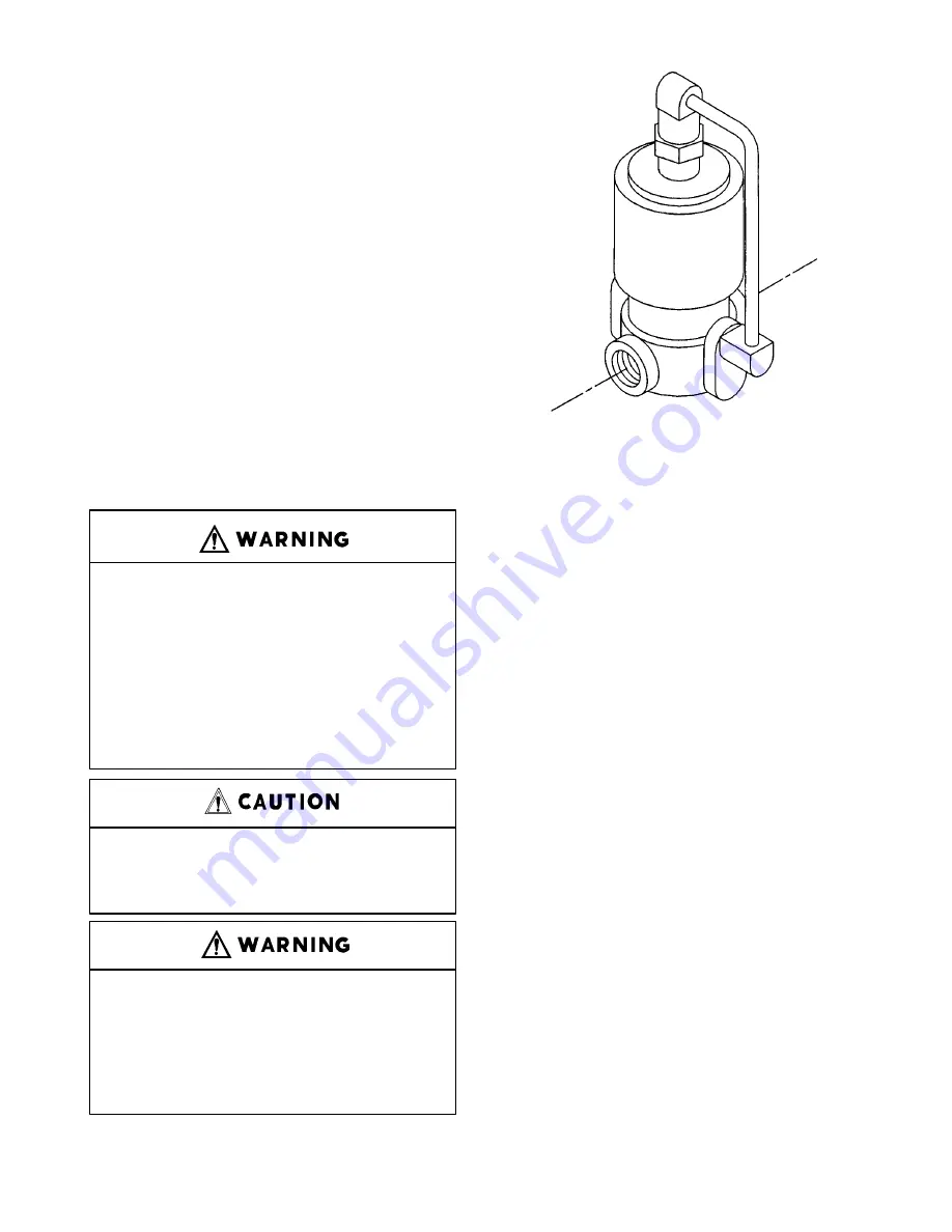
FIGURE 4–4 – BLOWDOWN VALVE
Blowdown Valve (FIGURE 4–4) – This valve normal-
ly is used for control functions, but also serves to relieve
reservoir pressure following a shutdown. The blow-
down valve is a two–way solenoid valve which is piped
into the oil reservoir outlet ahead of the minimum pres-
sure valve. When the solenoid is de–energized, the
valve opens and the coolant system is blown down.
When the solenoid is energized, the valve closes to al-
low the coolant system to pressurize. A control air
check valve is provided to ensure that the inlet valve is
closed during blowdown.
Oil Level Gauge (FIGURE 1–5, Section 1, page 3) –
This gauge is located on the oil reservoir and indicates
the oil level. See section 5 for information on how to
correctly read the gauge and proper lubrication.
Minimum Discharge Pressure/Check Valve
(FIGURE 4–5, page 32) – An internal spring–loaded
minimum pressure valve is used in the final discharge
line to provide a positive pressure on the coolant sys-
tem of the compressor even if the air service valve is
fully open to atmospheric pressure. This valve also
functions as a check valve to prevent back flow of air
from the shop air line when the unit stops, unloads, or
is shut down.
The valve incorporates a spring–loaded piston which
maintains approximately 65 psig in the oil reservoir.
When the air pressure on the upstream (reservoir) side
of the valve rises above 65 psig, the spring is overrid-
den and the valve opens to full porting.
The valve does not require maintenance or adjustment.
If the valve fails to function, check the valve stem O–
Содержание ELECTRA-SAVER EAYQ E
Страница 15: ...13 10 613 SP Page 6 DECALS 206EAQ077 212EAQ077 218EAQ077 211EAQ077 207EAQ077 ...
Страница 16: ...13 10 613 SP Page 7 DECALS 216EAQ077 217EAQ077 222EAQ077 221EAQ077 208EAQ077 ...
Страница 31: ...13 10 613 SP Page 22 FIGURE 4 2 FLOW CHART FOR SET UP PROGRAMMING ...
Страница 45: ...13 10 613 SP Page 36 FIGURE 4 10 CONTROL SCHEMATIC COMPRESSOR AT FULL LOAD 204EAY797 Ref Drawing ...
Страница 48: ...13 10 613 SP Page 39 FIGURE 4 13 WIRING DIAGRAM 202EAY546 Ref Drawing ...
Страница 75: ......


