background image

IdentiFlex 630 Installation and Operation Manual 

S

mart

S

tart Capable


9-25-96

44 

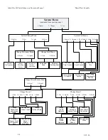
System Menu 

(continued from previous page) 

1=Display

2=Change

3=Test


System Change Menu 

1=Config

2=Dict

3=Cards

4=Misc.


Upload 

Configuration 

Change Dictionary Menu 

1=Words             2=Upload 

Change 

Dictionary 

Entries 

Upload New 

System 

Dictionary 

Change Card Menu 

1=Add  

       2=Delete


Add a New 

Card


Delete an 

Existing Card 

Change Miscellaneous Menu 

1=Menu1              2=Menu2


Change Menu 1


1=Pass    2=Codes    3=Date    4=Seq.    5=Baud    

Change 

Passwords 

and access 

levels

Change Input 
Group Codes


Change 

Time and Date


Change 

Access Level 

of Sequence 

Keys

Change Baud 

Rate of 

System 

Peripherals

Change Menu 2 

1=City     2=Sig Sil     3=Ann     4=Trbl     5=Dialer        6=Prefix


Change 

City Tie 

Operation


Change 

Annunciator 

Supervision


Change 

Automatic 

Silence Timing


Change 

Trouble 

Operation


Change 

To Dialer 

Mode of 

Operation

System Test Menu 

1=Inputs    2=Outputs   3=ID  4=Grnd   5=Lamp   6= Analog


Test Input  

Card Circuits


Test Output 

Card Circuits


Test Leakage 

 to Ground


Test System 

Lamps 

Test Card   

IDs


Test Analog 

Addressable  

Devices


Change Alarm 

Prefix 

Содержание Smart Start IDENTIFLEX 630

Страница 1: ...IDENTIFLEX 630 ANALOG ADDRESSABLE FIRE ALARM CONTROL PANEL INSTALLATION OPERATION MANUAL P N 71165 Revision 3 0 Issued 9 25 96...

Страница 2: ......

Страница 3: ...l is proprietary to The Gamewell Company Such information and technical drawings may not be copied or reproduced in any manner or disclosed to organizations that might be competitive to Gamewell witho...

Страница 4: ......

Страница 5: ...k of damage to the equipment we suggest using all Gamewell Components 4 There is no substitute for proper maintenance and testing of this or any life safety product Gamewell recommends testing and mai...

Страница 6: ......

Страница 7: ...ondition 13 Trouble Condition 14 INSTALLATION 15 IdentiFlex 630 System Housing 16 Hardware Assembly 16 Module Identification and Placement 18 Main Power Supply 19 Specifications 19 Interconnects 19 Op...

Страница 8: ...54 User Text Selection 54 Output Circuit Programming 56 Field Descriptions for Signal Circuits and Analog Addressable 58 Signal Circuit Types 59 Output Signal Circuit Type 59 Signal Circuit Restore 5...

Страница 9: ...Sil 84 Change Ann 84 Change Trbl 85 Change Dialer 85 Change Prefix 85 Test Menu 86 Test Input 86 Test Output 86 Test ID 86 Test Gnd 87 Test Lamps 87 Test Analog 88 COMPUTER LAPTOP PROGRAMMING OVERWIEW...

Страница 10: ...IF630 System Description 5 26 01 ___________________________________________________________________________________________...

Страница 11: ...Section 1 IDENTIFLEX 630 System Description...

Страница 12: ...with visual indications and guided prompts during all operating conditions All alarms faults or supervisory actions as well as system operating conditions Normal Alarms Faults are shown on the alphan...

Страница 13: ...to the battery Provisions for Brown Out protection are functional when the main AC power drops below a safe operating voltage level Operating from a 120 VAC source the main power supply mounts in the...

Страница 14: ......

Страница 15: ...IF630 System Operation Installation 5 26 01 ___________________________________________________________________________________________ Rev 3 0 5 Section 2 IDENTIFLEX 630 System Operation...

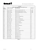
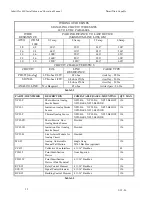
Страница 16: ...o the normal condition provided the cause of alarm has been eliminated The signal circuits city tie alarm relay and or supervisory relay will restore and the panel will return to the normal quiescent...

Страница 17: ...Drill feature has been activated ACKNOWLEDGE The Acknowledge LED yellow will flash to indicate the next action is to press the ACK switch SUPERVISORY ALARM The Supervisory LED yellow indicates a super...

Страница 18: ...s if the priority interrupt is set 2 The system defaults to Security Level 2 Acknowledge Signal Silence and Reset Switches are accessible without a password 3 Whenever any input point s goes into alar...

Страница 19: ...tamped record of the event s occurrence In the event of multiple alarms the alphanumeric display can be scrolled using the up down arrow keys to show all active initiating devices 3 The red Alarm LED...

Страница 20: ..._____________________________ Signal Silence In the Alarm condition the red LED for SIGNAL SILENCE will begin to flash This guided prompt feature notifies the user that it is possible but not necessar...

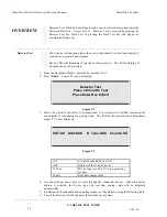
Страница 21: ...presses the RESET switch the following actions will occur 1 The LCD Display will announce the System Reset Refer to Figure O 4 2 If no further alarms exist in the system all signal circuits will deac...

Страница 22: ...d all automatic detectors connected to the device are subject to the alarm verification cycle Any two wire automatic detectors reporting an alarm condition programmed for verification will start the p...

Страница 23: ...ble indicator will be silenced If a subsequent supervisory alarm should occur in a different supervisory alarm zone the alphanumeric display will annunciate the new point and the system common signal...

Страница 24: ...ffer to provide a time stamped record of the event s occurrence When the Acknowledge button is depressed the system trouble audible is silenced and the system trouble LED remains illuminated Should an...

Страница 25: ...IF630 System Operation Installation 5 26 01 ___________________________________________________________________________________________ Rev 3 0 15 Section 3 IDENTIFLEX 630 Installation...

Страница 26: ...Analog Addressable System Table 1 Installation Wiring Diagrams ____________________________________________________________________________________________ Hardware Assembly NOTE Upon receiving the c...

Страница 27: ...sis Clean as required 6 Mount the main chassis to the cabinet studs and secure hex nuts 7 Connect all field wiring Referenced drawing D W1145 Wiring IF630 Analog Addressable System as required or D W1...

Страница 28: ...ction of the system Specifically the electronic module functions are identified These card location numbers reference hardwired physical circuits Card identification numbered 0 through 3 reference des...

Страница 29: ...terconnects to J16 on bus driver module J2 connector Interconnects to J12 on bus driver module 5V 12V and 24V supervision Operators Display The Operators Display OD is the main interface to system The...

Страница 30: ...__________________________________________________ CPU Module The CPU module or microprocessor module contains the system operating firmware and non volatile memory It provides all the system memory a...

Страница 31: ...hange S6 Open Do Not Change S7 S8 Open 9600 Baud Rate Auto Detect Baud S7 S8 Closed 4800 Baud Rate S7 Open S8 Closed 2400 Baud Rate S7 Closed S8 Open 1200 Baud Rate DIP Switch SW1 Table The LED s on t...

Страница 32: ...cuit City Tie Programming The bus driver module contains three jumpers for city tie programming J1 J2 J3 located in the center of the board These three jumpers are used to select the reverse polarity...

Страница 33: ...tem initialization determines if the feedback loop is utilized A feedback circuit must have less than 50 ohms in loop resistance The function of relays K1 K4 Relay K1 Common Alarm Relay K2 Common Trou...

Страница 34: ...es housed in the common control section the operators display module the bus driver module a relay expander card and the CPU module Common Control Input Power 24VDC Quiescent Current 275 mA Alarm Curr...

Страница 35: ...ns for master box or line reversal option terminal 8 M2 Signal Circuit 1 Signal CCT 1 24V 2A Style Y or Z Style Y requires 3 9K ohm end of the line resistor terminal 9 1L1R Style Z Return terminal 10...

Страница 36: ...uble is remedied programmable 7 2 C Form C Trouble relay common contact 10A 30 VDC or 230 VAC fused 10 amps 8 2 M Alarm relay feedback point to monitor status of controlled device RELAY 3 COMMON SUPER...

Страница 37: ...e system uses a 12 point field wiring terminal strip The main board with the micro controller and two channel driver circuits draws 35mA from the 24V supply not allowing for any draw by devices on the...

Страница 38: ...24 vdc Terminal 8 24 R 24 vdc return Block 9 L1 Common optional 10 L1R Common return 11 L2 Data 12 L2R Data return Analog Circuit Wiring Requirements and Limitations 1 Cable length per circuit 4 000 f...

Страница 39: ...ard electrical backboxes When monitoring other contact devices the unit can be mounted in a standard double gang back box PID 95P is a PID 95 mounted on a 4 11 16 plastic plate where visual identifica...

Страница 40: ...2 CH CF1 IS 24 CFW Chime SS Vib White 245 71303 CH DF1 IS 24 VFR Chime SS Vib Red 245 71548 SM 12 24 R Single Circuit Sync Module 025 71549 DSM 12 24 R Dual or Class A Sync Module 038 70871 MIZ 24 R M...

Страница 41: ...ync 096 71551 SR 2415 VFR Strobe 15 Cd Sync 096 71569 RSP 241575 VFR Strobe 15 75 Cd Plate Mount 100 71554 SRP 241575 VFR Strobe 15 75 Cd Plate Mount Sync 138 71555 SR 241575 VFR Strobe 15 75 Cd Sync...

Страница 42: ...MOUNTING QTY MAX XP95 P Photo Electric Analog Smoke Sensor XP95 B4 XP95 B6 XP95 B6LOW XP95 B6R4 XP95 B6SNDR 126 XP95 I Ionization Analog Smoke Sensor XP95 B4 XP95 B6 XP95 B6LOW XP95 B6R4 XP95 B6SNDR 1...

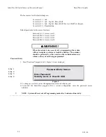
Страница 43: ...is displayed see Figure I 2 Status RESET 00 00 94 00 00 Commencing System Reset Figure I 2 3 After the initial system startup is completed the display will show the current date month day year and tim...

Страница 44: ......

Страница 45: ...IF630 System Test Mode 5 26 01 ___________________________________________________________________________________________ Rev 3 0 35 Section 4 IDENTIFLEX 630 System Test Mode...

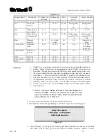
Страница 46: ...now displayed Detector Test Press a Circuit to Test Press Enter Key to Exit Figure T2 3 Select the circuit of the device to be monitored Use circuit select switches located on the zone display for th...

Страница 47: ...e utilized Testing the system in the Walk Test mode enables one person to test the system without the aid of another to confirm activation and reset the panel Activation i e detected ALARM or TROUBLE...

Страница 48: ...red devices have been selected Press Enter Walk Test Output Circuit Press an Output Circuit to Walk Test Press the Enter Key to Exit Figure T5A 9 The system will now prompt you for a signal circuit to...

Страница 49: ...cleared 12 To clear Walk Test operation each device and output must be individually taken out of Walk Test This is accomplished in the same manner as described in steps 1 10 above Each device must be...

Страница 50: ...elected the device type zone type and zone status will be displayed automatically 5 Use the left right arrow keys to move to the Bypass status field 6 Use the up down arrow keys to select NOT BYPASSED...

Страница 51: ..._________________________________________________________________________ Rev 3 0 41 Status FAULT xx xx 95 xx xx System I O s Bypassed Figure T10 13 To reactivate Bypassed devices repeat steps 1 11 to...

Страница 52: ...IdentiFlex 630 Installation and Operation Manual SmartStart Capable 9 25 96 42 Section 5 IDENTIFLEX 630 Programming...

Страница 53: ...ktes 2 Bypass 3 Input 4 Output Walk Test Menu 1 Disp 2 Prog Bypass Menu 1 Disp 2 Prog Input Device Test Program Walk Test Display Walk Test Program Bypass Display Bypass System Display Menu 1 Config 2...

Страница 54: ...Menu 1 1 Pass 2 Codes 3 Date 4 Seq 5 Baud Change Passwords and access levels Change Input Group Codes Change Time and Date Change Access Level of Sequence Keys Change Baud Rate of System Peripherals C...

Страница 55: ...rcuit tables that store the information for all of the 126 maximum devices on each circuit The circuit table is then further divided into an input table and an output table Input tables consist of all...

Страница 56: ...Option Use Right and Left arrow keys to horizontally scroll and select option field To Select Field Variable Types Use up and down arrows keys to vertically scroll variable types Keypad prompts Keypad...

Страница 57: ...y standby power source NOTE It is assumed all system installation wiring procedures detailed in this manual have been completed in accordance with local state and federal codes Initial System Startup...

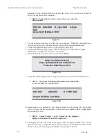
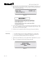
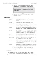
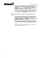
Страница 58: ...ill flashing press the Power On switch Figure 3 will be displayed 3 A Warning Message will be displayed If no action is taken the system will continue its reset process To Initialize System to Default...

Страница 59: ...pped with a built in screen saver When the system remains in a idle mode i e normal quiescent condition for over 15 seconds the screen will automatically go blank Status Normal XX XX 94 xx xx System I...

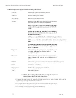
Страница 60: ...he system will not recognize an alarm or trouble condition The premises should be protected by a fire watch or other reliable measure s whenever the system is being programmed Password Entry 1 Press P...

Страница 61: ...CIRCUIT PROGRAMMING Select Circuit Prog from the main Programming Mode menu to modify input output device characteristics e g zone type group assignment signal code and device specification text Figu...

Страница 62: ...ensated to the environment The device sensitivity range 3 is the least sensitive and 0 is the most sensitive The default is 2 If the device is a heat detector Figure 8B will be displayed If the device...

Страница 63: ...ive device setting and the number 3 is the least sensitive device setting Refer to Figure 8A Ckt XX Add XXX D_Type Opt Z_Type XXX I_Grp XXX Sens X Comp X Figure 8A 4 2 To change an optical detector to...

Страница 64: ...om text word dictionaries W1 through W5 The represents the text entry number in dictionary D See Figure 10 NOTE The WD field is not displayed until the cursor is placed in its field When the dictionar...

Страница 65: ...All the device control functions are active without placing the system in a general alarm condition at the panel And And Initiating Zone Two stage automatic detection see Glossary Ack Acknowledgment...

Страница 66: ...Floor Closet Level Floor Service Elevator Lobby Sub level Basement Level Sub basement Level Basement Parking Level Garage Level Wing Floor Wing Atrium Mezzanine Ballroom Kitchen 1 2 3 4 5 6 7 8 9 10...

Страница 67: ...ig xxxx Res xxx Drl x Sil x Figure 11 3 2 When an analog addressable line is selected for programming from the operators display Figure 11B The yellow LED of the selected circuit will illuminate Ckt x...

Страница 68: ...matic detection device area spacing is no more than one half that determined by the application of NFPA 72 Chapter 5 Sig xxx Indicates the type of signaling to be output by the circuit i e steady marc...

Страница 69: ...circuit is returned to Idle E CALIFORNIA UNIFORM FIRE CODE California Uniform Fire Code Signal circuits when activated will provide a 24 VDC output in Marchtime 120 format for 10 seconds on and 5 sec...

Страница 70: ...t Alarm or 2nd Alarm These levels designate at which level of alarm an output circuit will activate Output circuits assigned to 1st alarm level system default will activate when a first alarm is detec...

Страница 71: ...ime out feature will reset its timer to silence its associated outputs at ten 10 minutes past the last alarm C Drillable Any signal circuit programmed as drillable will activate when the drill feature...

Страница 72: ...ed in Control By Event data base programming is protected and cannot be altered or damaged 1 From the circuit programming display menu select the 3 numeric key 2 Press Enter Figure 12 C is displayed A...

Страница 73: ...or each device or circuit there is a field Alr for assigning the Alarm level it will activate The three levels of alarm 1 pre alarm 2 1st alarm and 3 2nd alarm These levels combined with the CBE table...

Страница 74: ...r and press Enter The group number is not shown and is then canceled xxx xxx xxx xxx xxx xxx xxx xxx xxx xxx xxx xxx xxx xxx xxx xxx Enter Input Group xxx Figure 14A __________________________________...

Страница 75: ...ter up to 256 group output numbers see Figure 15B NOTE To cancel an individual output group enter that group number and press Enter The group number is not shown and is then canceled xxx xxx xxx xxx x...

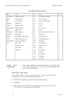
Страница 76: ...evels of programming the system will be in an off line status System Menu The System Menu menu is displayed when the programming password is entered System Menu 1 Display 2 Change 3 Test 0 Exit Displa...

Страница 77: ...ant Card 16 ID FF is Vacant Card 17 ID FF is Vacant Press Enter Key To Continue System Configuration Modular Placement Select this field to view the system modular placement hardware configuration car...

Страница 78: ...SmartStart Capable 9 25 96 68 Common Control Section Cards 0 7 Left Display Cards Left I O Cards Right I O Cards Right Display Card 12 8 16 20 13 9 17 AAM 21 14 10 18 22 15 11 19 23 Table L3 IF630 Ca...

Страница 79: ...ly supervision 24 V 12V 12V 5V supervision V battery to power supply unregulated raw supply system on AC Battery Charging Monitor battery monitor aux 1 2 Analog Addressable Module Card 17 09 XP95 anal...

Страница 80: ...figuration File To Download 1 Press PgDn 2 Choose 7 ASCII 3 Enter Filename NOTE For Procomm only the ASCII transfer setup must have the following parameters Use the following table ASCII Upload To Dow...

Страница 81: ...communications software When using alternate software packages follow the procedure required for that software to receive an ASCII file The next CR the system receives will start the transmission of t...

Страница 82: ...are assigned to each of the function keys The following display are the default settings for the Flex 600 system Display Menu 1 Config 2 Dict 3 Event 4 Misc 0 Exit 4 Display Menu Misc 1 Pass 2 Codes 3...

Страница 83: ...56 33 123456 34 123456 35 123456 36 123456 37 123456 38 123456 39 123456 40 123456 41 123456 42 123456 43 123456 44 123456 45 123456 46 123456 47 123456 48 123456 49 123456 50 123456 51 123456 52 1234...

Страница 84: ...enu Misc 1 Pass 2 Codes 3 Ver 4 Ram 0 Exit 3 Flex 620 System Version 1 0 Last Updated on Mar 14 1995 at 15 43 58 Press Enter Key To Continue Display RAM Displaying the RAM allows the user to view the...

Страница 85: ...e followed When using the PROCOMM software package the following settings should be configured Change Menu 1 Config 2 Dict 3 Card 4 Misc 0 Exit 1 Ready to Upload Configuration File To Upload 1 Press P...

Страница 86: ...hand corner of the display To select the second letter of that word press the Letters Numbers key until a2 is displayed a3 should be displayed if the third letter is desired and should be displayed i...

Страница 87: ...ach dictionary The following lines would contain the desired text entries in numerical order for dictionary 1 When all of the entries for dictionary 1 have been entered two fore slashes should be inse...

Страница 88: ...Room Room 111 Room 112 Below Raised Floor NOTE For Procomm only the ASCII transfer setup must have the following parameters Use the following table ASCII Upload To Down Load 1 Echo locally No 1 Press...

Страница 89: ...location the existing card should be deleted before the new card is added This will ensure that the control by event table is up to date Change Menu 1 Config 2 Dict 3 Card 4 Misc 0 Exit 3 Change Card...

Страница 90: ...gned to that password is defined NOTE Before changing the password 4 programming password make sure that you have added a new password to access the programming Sec 4 area Change Menu Misc 1 Menu1 2 M...

Страница 91: ...s entered individually After the code has been entered a sub menu appears This menu allows you to change the Timing the number of Cycles and the output of the signal circuits after the code is complet...

Страница 92: ...lows the user to redefine the access levels associated with each of the sequence keys Each of these keys is assigned an access level by default The Acknowledge key is assigned to level 1 access The Re...

Страница 93: ..._ abcdefghijklmnopqrstuvwxyz 0123456789 AB CDEFGHIJKLMNOPQRSTUVWXYZ _ abcdefghijklmnopqrstuvwxyz 0123456789 ABCDEFGHIJKLMNOPQRSTUV WXYZ _ abcdefghijklmnopqrstuvwxyz 0123456789 ABCDEFGHIJKLMNOPQRSTUVW...

Страница 94: ...Menu Misc 1 Menu1 2 Menu2 0 Exit Change Menu 2 1 City 2 Sig Sil 3 Ann 4 Trbl 5 Dialer 6 Prefix 0 Exit 1 Press Enter Key To Exit Press Any Other Key To Toggle City Tie Is In Standard Mode City Tie Is...

Страница 95: ...s the system to delay the reporting of AC failure as required by UL when the Dialer Is Installed is selected Normal reporting of AC failure troubles is restored when the Dialer Is Not Installed option...

Страница 96: ...he Output Test is used to test the interaction between an input circuit and an output circuit When selected the user is prompted to enter the output card location number to be tested Then the input ca...

Страница 97: ...39 FF Test Gnd The Gnd Ground test utilizes a unique method of ground detection A measurement is taken from the 5 supply to earth ground and a value is displayed Then a measurement from system common...

Страница 98: ...r the desired state is the number that should be entered at the Data to Send prompt When this information is entered the system displays the real time information including CCT Address Device type and...

Страница 99: ...Opt Photo Detector non comp 0 9 10 40 41 44 45 54 55 127 Opt Photo Detector Compensated 0 9 10 40 41 44 Background sensitivity 6 8 Background sensitivity 6 18 Heat Thermal Detector 0 9 10 Fixed Value...

Страница 100: ...Parity 8 Data Bits and 1 Stop Bit NOTE Most standard communication packages for computers will allow you to set the proper protocol for the communications port of your computer PROCOMM SOFTWARE Config...

Страница 101: ...L E OFF General Setup From the Procomm SETUP MENU select option 4 to display the GENERAL SETUP menu The following settings should be displayed 1 Editor name 2 Default d l path 3 Default log file PROCO...

Страница 102: ...on alarm trouble and system status changes It can also aid in troubleshooting by providing detailed information of system faults Access Levels System access levels may be accessed via the computer By...

Страница 103: ...IF630 Programming 5 26 01 ___________________________________________________________________________________________ Rev 3 0 93 Section 5A IDENTIFLEX 630 Appendix...

Страница 104: ...utputs 8 Status I O being bypassed 9 Status bypassed I O being restored 10 Status zone being Trouble tested 11 Status zone being Alarm tested 12 Alarm zone in verification sequence 13 Alarm Reserved f...

Страница 105: ...limits 31 Trouble 24 volts on CCT 6 7 off limits 32 Trouble 5 volts on card OK 33 Trouble 24 volts on card 0 1 OK 34 Trouble 24 volts on card 2 3 OK 35 Trouble 24 volts on card 4 5 OK 36 Trouble 24 vo...

Страница 106: ...lex 630 Installation and Operation Manual SmartStart Capable 9 25 96 96 48 Trouble analog channel in Class B operation 49 Trouble LCD malfunction 50 Status system in walktest 51 Status system out of w...

Страница 107: ...IDENTIFLEX 600 Stand Alone Panel FIRMWARE VERSION R7 MANUAL SUPPLEMENT GAMEWELL 60 PLEASANT STREET P N 71956 ASHLAND MA 01721 ISSUE 1 06 16 2000...

Страница 108: ...IF 600 Firmware Version R7 Manual Supplement Issue 1 06 16 2000 ii This page intentionally blank...

Страница 109: ...TERIAL The information contained in this manual is proprietary to Gamewell Such information and technical drawings may not be copied or reproduced in any manner or disclosed to organizations that migh...

Страница 110: ...IF 600 Firmware Version R7 Manual Supplement Issue 1 06 16 2000 iv This page intentionally blank...

Страница 111: ...ol panels to verify compatibility To maximize system performance and minimize risk of damage to the equipment we recommend using all Gamewell components 3 There is no substitute for proper maintenance...

Страница 112: ...IF 600 Firmware Version R7 Manual Supplement Issue 1 06 16 2000 vi This page intentionally blank...

Страница 113: ...y Trouble Displays 3 All Input Walk Test 3 Expanded RAN SAN Supervision 3 Auto Silence Timeout 3 Silence Inhibit 3 Building Control Switch Supervision 3 Building Control Display Placement 4 Walk Test...

Страница 114: ...n 36 Field Descriptions 37 Device Selection 38 Heat Device Operating Selection 38 Zone Type Selection 39 Initiating Group Selection 39 User Text Selection 39 Output Circuit Programming 41 Field Descri...

Страница 115: ...Code 62 Change Date 63 Change Seq 64 Change Baud 64 Baud Rate Switch Settings 64 Change City 66 Change Ann 66 Change Trbl 67 Change Bldg Control Switch Supervision 67 Change Day Enable 67 Change Day N...

Страница 116: ...SOFTWARE 81 Configuration 81 Line Settings 81 Setup Menu 81 Terminal Setup 81 General Setup 82 ASCII Transfer 83 SYSTEM MONITORING CONTROL 83 Status Monitoring 83 Access Levels 83 Control Strings 83 C...

Страница 117: ...Section 1 IF 600 FIRMWARE VERSION R7 MANUAL SUPPLEMENT Introduction...

Страница 118: ...IF 600 Firmware Version R7 Manual Supplement Issue 1 06 16 2000 2 This page intentionally blank...

Страница 119: ...nd programmable Pre release Abort and Dump Water Zone Allows inputs to be designated as Water Flow with programmable delays and selectable silencing Daylight Savings time Allows automatic correction o...

Страница 120: ...laptop computer using the Gamewell Ver R7 Laptop program PN 31021 01 Run the conversion routine in the program to convert the configuration file to a version r7 file Before removing or installing any...

Страница 121: ...IF 600 Firmware Version R7 Manual Supplement Issue 1 06 16 2000 5 Figure G 1 Processor Card U5 6XXXXXXX LO U4 6XXXXXXX HI...

Страница 122: ...IF 600 Firmware Version R7 Manual Supplement Issue 1 06 16 2000 6 This page intentionally blank...

Страница 123: ...Section 2 IF 600 FIRMWARE VERSION R7 MANUAL SUPPLEMENT Special System Functions...

Страница 124: ...IF 600 Firmware Version R7 Manual Supplement Issue 1 06 16 2000 8 This page intentionally blank...

Страница 125: ...is activated Upon deactivation of the switch the counter will resume from where it was paused Only one activation of the Abort switch is recognized Subsequent activations will have no effect on the R...

Страница 126: ...as an Abort zone and Assign Input Group X Select the input device for the Dump switch program it as a Dump zone and Assign Input Group X Output Devices Select the Signal Circuit Conventional to sound...

Страница 127: ...Section 3 IF 600 FIRMWARE VERSION R7 MANUAL SUPPLEMENT System Test Mode...

Страница 128: ...IF 600 Firmware Version R7 Manual Supplement Issue 1 06 16 2000 12 This page intentionally blank...

Страница 129: ...RM or TROUBLE signal in the initiating device will cause the panel to log the event and activate all associated indicating circuits if programmed The device is reset after four 4 seconds Activation of...

Страница 130: ...ct the device address When the device address is selected the device type zone type and zone status will be displayed automatically 5 Use the left right arrow keys to move to the Walk Test status fiel...

Страница 131: ...igure T6 WARNING If the system is in Walk Test mode and a device not in the test mode is activated the system will go into alarm and all output circuits will be activated 12 To clear Walk Test operati...

Страница 132: ...tch or other reliable means should be employed to monitor the unprotected area 3 Select Display 1 to display the circuits input and output that are currently in the Bypass mode 4 Select Prog 2 to sele...

Страница 133: ...for each device to be Bypassed 11 When all desired input devices have been selected press Enter 12 Repeat steps 3 8 to bypass outputs 13 Press the Enter key Then exit the test menu by depressing 0 th...

Страница 134: ...or enter the number and press the ENTER key 4 Repeat this process until all of the desired Devices are assigned to ByPass Groups 5 Press the Enter key to exit the menu to active or deactivate ByPass...

Страница 135: ...2 1 Press 3 and then Enter 2 Figure T3 is now displayed CKT XX Add XXX D_Type XXX Counts XX Figure T3 CCT Circuit of selected device 1 4 Add Address of the selected device D_Type Device type see table...

Страница 136: ...Value NA NA Above Fixed Value CZI or CZII CZI 95 0 16 17 54 NA NA 55 122 2nd Alarm above 122 PID or MAN PID 95 or MS 95 0 9 10 54 N A N A 55 127 REL RCE 95 0 14 15 45 NA NA 46 127 RSM RSM 95 0 14 15...

Страница 137: ...ion and current detector values Function Programming 1 Walk Test 2 Bypass 3 Input Test 4 Output Test 5 Display 0 exit 5 Display 1 Config 2 Dict 3 Events 4 Misc 5 Detectors 0 Exit Display 1 Config 2 Di...

Страница 138: ...tionary Menu 1 Display 2 Download 3 Exit Display 1 Config 2 Dict 3 Events 4 Misc 5 Detectors 0 Exit 3 Events The Events Menu allows viewing of the system events log Use up down keys to scroll Press En...

Страница 139: ...e programmed Codes Use up down keys to scroll Press Enter key to Exit Tally The Menu Menu allows selection of either viewing or downloading the 30 day accumulated tally of Verification events that did...

Страница 140: ...The Mem Display shows the available Random Access Memeory Unallocated Bytes of Ram 206123 Press Any Key To Continue Display 1 Config 2 Dict 3 Events 4 Misc 5 Detectors 0 exit 4 Detectors The Display...

Страница 141: ...Section 4 IF 600 FIRMWARE VERSION R7 MANUAL SUPPLEMENT Programming...

Страница 142: ...IF 600 Firmware Version R7 Manual Supplement Issue 1 06 16 2000 26 This page intentionally blank...

Страница 143: ...ts Sig 3 Devices 4 Clear 2 Bypass 1 Display 2 Program 1 Device 2 I 0 Groups 3 Circuits 4 Bypass groups 1Assign devices to grp 2 Act Deact Groups 3 Test input devices 4 Test output devices 5 Display 1...

Страница 144: ...1 Download 2 Change 1 Menu 1 1 Pass Codes 2 Initiating codes 3 Time date 4 Access level 5 Baud rate 2 Menu 2 1 City Select MB LR Chicago Dialer 2 Ann Supervision 3 I O troubles 4 BC Key 5 Day Enable...

Страница 145: ...IF 600 Firmware Version R7 Manual Supplement Issue 1 06 16 2000 29 3 Test 1 Inputs 2 Outputs 3 Card I D 4 Ground fault 5 Lamp test 6 Analog test...

Страница 146: ...ircuit table is then further divided into an input table and an output table Input tables consist of all initiating devices detectors pull stations etc while the output table consists of all the actua...

Страница 147: ...Use Right and Left arrow keys to horizontally scroll and select option field To Select Field Variable Types Use up and down arrows keys to vertically scroll variable types Keypad prompts Keypad promp...

Страница 148: ...ssumed all system installation wiring procedures detailed in this manual have been completed in accordance with local state and federal codes Initial System Startup 1 Activate main power The Power ON...

Страница 149: ...el X User ID XXX Figure 3 3 Enter a Level 4 password If an invalid password is entered or no password is entered the system will go into normal reset and skip the SmartStart 4 If the password is accep...

Страница 150: ...military see Figure 4 NOTE The system is equipped with a built in screen saver When the system remains in a idle mode i e normal quiescent condition for over 15 seconds the screen will automatically...

Страница 151: ...NG When the system is in access level 4 programming the system will not recognize an alarm or trouble condition The premises should be protected by a fire watch or other reliable measure s whenever th...

Страница 152: ...m System Wide Programming 0 Exit Exit PROGRAMMING MODES TABLE P1 Circuit Programming Select Ckt Prog from the main Programming Mode menu to modify input output device characteristics e g zone type gro...

Страница 153: ...nvironment The device sensitivity range 3 is the least sensitive and 0 is the most sensitive The default is 2 If the device is a heat detector Figure 8B will be displayed If the device is a heat detec...

Страница 154: ...user to select a range of settings which are numeric values 0 through 3 The number 0 is the most sensitive device setting and the number 3 is the least sensitive device setting Refer to Figure 8A Ckt...

Страница 155: ...the up down arrow keys or enter the three digit word number to select text entries from text word dictionaries W1 through W5 The represents the text entry number in dictionary D See Figure 10 NOTE Th...

Страница 156: ...ion acknowledgment SigSil Signal Silence Remote location Signal Silence Drill Drill Remote drill system condition Reset Reset Remote reset of the panel resets system Abort Abort Delays or stops discha...

Страница 157: ...loset Level Floor Service Elevator Lobby Sub level Basement Level Sub basement Level Basement Parking Level Garage Level Wing Floor Wing Atrium Mezzanine Ballroom Kitchen 1 2 3 4 5 6 7 8 9 10 11 12 13...

Страница 158: ...ure 11 3 2 When an analog addressable line is selected for programming from the operators display Figure 11B The yellow LED of the selected circuit will illuminate Ckt xxx Add xxx D_Type xxx Alr XX O_...

Страница 159: ...tected space c Automatic detection device area spacing is no more than one half that determined by the application of NFPA 72 Chapter 5 Sig xxx Indicates the type of signaling to be output by the circ...

Страница 160: ...activated will provide a 24 VDC output in the pattern of a Morse Code U This pattern is active for 25 seconds off for 25 seconds active for 25 seconds off for 25 seconds active for 25 seconds off for...

Страница 161: ...estore on RESET Any active output programmed to restore on RESET will not restore on any other action NOTE There are a few restrictions to be aware of regarding output signal circuits 1 The two signal...

Страница 162: ...silence its associated outputs after the programmed delay C Drillable Any signal circuit programmed as drillable will activate when the drill feature is activated Restoring Outputs A Restore On ACKNOW...

Страница 163: ...t XXX Address XXX Figure 12D CONTROL BY EVENT Control by Event programming allows the user to create a matrix whereby selected groups of input devices are logically connected to selected groups of out...

Страница 164: ...keys enter the corresponding input group number The group number will be displayed in the location as shown in Figure 14 xxx Enter Input Group xxx Figure 14 4 Enter all desired input group numbers Th...

Страница 165: ...roup 5 Press Enter Figure 15 is now displayed Enter Output Group XXX Figure 15 6 Using numeric keys enter the desired output group number or press the signal circuit switch The assigned output group n...

Страница 166: ...are sequentially arranged ascending order Enter up to 256 group output numbers see Figure 15B NOTE To cancel an individual output group enter that group number and press Enter The group number is not...

Страница 167: ...IF 600 Firmware Version R7 Manual Supplement Issue 1 06 16 2000 51 FUNCTION PROGRAMMING See System Test Mode...

Страница 168: ...amming the system will be in an off line status System Menu The System Menu menu is displayed when selected from the programming mode menu System Menu 1 Display 2 Change 3 Test 0 Exit Display Menu Sel...

Страница 169: ...Card 7 ID FF is Vacant Card 8 ID FF is Vacant Card 9 ID FF is Vacant Card 10 ID FF is Vacant Card 11 ID FF is Vacant Card 12 ID FF is Vacant Card 13 ID FF is Vacant Card 14 ID FF is Vacant Card 15 ID...

Страница 170: ...t power supply supervision 24 V 12V 5V supervision V battery to power supply unregulated raw supply system on AC Battery Charging Monitor battery monitor aux 1 2 Analog Addressable Module Card 17 09 X...

Страница 171: ...llow the procedure required for that software to receive an ASCII file The next CR the system receives will start the transmission of the file Configuration Menu 1 Display 2 Download 0 Exit 2 Ready to...

Страница 172: ...ary 3 End of Dictionary 3 Start of Dictionary 4 End of Dictionary 4 Start of Dictionary 5 End of Dictionary 5 Press Enter Key to Continue Download Dict Selecting Download from the Display Dictionary M...

Страница 173: ...ss 2 Codes 3 Tally 4 Ver 5 Ram 0 Exit Display Pass Displaying the passwords allows the user to view the 10 passwords that are assigned to the system Each password has a user ID and a security or acces...

Страница 174: ...123456 36 123456 37 123456 38 123456 39 123456 40 123456 41 123456 42 123456 43 123456 44 123456 45 123456 46 123456 47 123456 48 123456 49 123456 50 123456 51 123456 52 123456 53 123456 54 123456 55...

Страница 175: ...Misc Display Menu Misc 1 Pass 2 Codes 3 Tally 4 Ver 5 Ram 0 Exit 4 610 System Version 7 00 Last Updated on Oct 10 1999 at 15 43 58 Press any Key To Continue Display RAM Displaying the RAM allows the...

Страница 176: ...Change Menu The system change menu allows the user to change various system parameters Change Menu 1 Change Menu 1 Menu 1 2 Menu 2 3 Menu 3 4 Menu 4 0 Exit Change Menu 1 Menu 1 2 Menu 2 3 Menu 3 4 Men...

Страница 177: ...make sure that you have added a new Security Level 4 password to access the programming area Change Menu 1 Menu 1 2 Menu 2 3 Menu 3 4 Menu 4 0 Exit 1 Change Menu 1 1 Pass 2 Code 3 Date 4 Seq 5 Baud 0...

Страница 178: ...code has been entered a sub menu appears This menu allows you to change the Timing the number of Cycles and the output of the signal circuits after the code is complete silence or March Time signal C...

Страница 179: ...Baud 0 Exit 3 Date Menu 1 Date 2 Time 3 Savings 1 THR Date 09 30 99 Time 09 52 41 Enter Month 09 Enter Date 30 Enter Year 99 Enter Day 1 SUN 2 MON 3 TUE 4 WED 5 THR 6 FRI 7 SAT 0 EXIT 5 Enter Date Men...

Страница 180: ...hange Baud selection will cause the system to output a printer test pattern to the RS 232 port This continuous output allows the user to select the baud rate of the connected device without having to...

Страница 181: ...e S3 Always Closed Do Not Change S4 Open Do Not Change S5 Open Do Not Change S6 Open Do Not Change Note P2 baud rate of is selected via S7 and S8 Auto Detect Baud rate is utilized for peripheral devic...

Страница 182: ...e condition the Spare relay will transfer for use with a local indicator which indicates that troubles and alarms can t be transmitted In the Dailer mode AC loss troubles are delayed for 6 hours to pr...

Страница 183: ...Change Bldg Control Switch Supervision The change BC Key option allows the selection of supervision of the Building Control 3 position switches When enabled any BC switch that is off of the Auto middl...

Страница 184: ...o You Want To Modify Y N Y Enter Time To Exit Day Mode Enter Hour 18 Enter Minutes 30 Enter Day Mode Exit Time Is Currently 18 30 Change Menu 3 Change Menu 1 Menu 1 2 Menu 2 3 Menu 3 4 Menu 4 0 Exit 3...

Страница 185: ...any key to continue Change Configuration Name The Change Config name option allows a textual designation of the configuration file for archive identification Change Menu 3 1 Abort 2 Prefix 3 Config 4...

Страница 186: ...ig 4 Tally 5 Sil Inh 6 AutoSil 0 Exit 5 Sil Inh Delay Is Set To 0 Min Enter New Signal Sil Delay 0 10 Delay Entry 0 10 X 30 sec Change Auto Silence Delay The Change Auto Sil Delay option allows the se...

Страница 187: ...ictable operation of the panel Change Menu 4 1 Cfg 2 Water 3 Relse 4 Dump 5 Dict 6 Card 0 Exit 1 If network upload will start at this point Ready to Upload Configuration File To Upload 1 Press PgUp 2...

Страница 188: ...hroug a P C connected through the serial port or from the Master in a network Change Menu 4 1 Cfg 2 Water 3 Relse 4 Dump 5 Dict 6 Card 0 Exit 5 Change Dictionary Menu 1 Words 2 Upload 0 Exit Change Di...

Страница 189: ...ey a1 should be displayed in the upper right hand corner of the display To select the second letter on a key press the Letters Numbers key until a2 is displayed a3 should be displayed if the third let...

Страница 190: ...13 Upload Dictionary Uploading is accessed by selecting 2 from the Change Dictionary Menu In order to upload a new dictionary a file containing the new dictionary entries must be created using an ASCI...

Страница 191: ...is also signified by two fore slashes Some important points to keep in mind when writing the file are as follows Dictionary 1 through dictionary 4 may contain up to 128 entries 0 127 Dictionary 5 may...

Страница 192: ...nge Card menu is selected an Add or Delete option is then prompted Select the desired option and enter the card number to be changed See system configuration in the installation section of this manual...

Страница 193: ...it cards and monitor for circuit noise This selection requires the input of the card location number see installation section for card location numbers to be tested The card is continuously scanned an...

Страница 194: ...21 USM 8 display is selected the corresponding signal circuit will activate when the display switch is pressed NOTE When card 0 main display is selected on the 630 and 650 systems no input card optio...

Страница 195: ...t Menu 1 Input 2 Output 3 ID 4 Gnd 5 Lamp 6 Analog ork 0 Exit 5 Press enter to continue Test Analog The analog test is designed to allow the user to control and obtain real time information about indi...

Страница 196: ...k Background Dirty Pre Alarm on 1st Alarm Shorted Ion Ionization Detector 0 9 10 40 41 44 Background 26 Background 36 Opt Photo Detector non comp 0 9 10 40 41 44 25 sensitivity 6 8 25 sensitivity 6 18...

Страница 197: ...port of your computer PROCOMM SOFTWARE Configuration When using PROCOMM to communicate with your IF 610 system the following configuration should be used Several areas of the Procomm setup menu and th...

Страница 198: ...ath 3 Default log file PROCOMM LOG 4 Screen dump file PROCOMM IMG 5 Screen write method DIRECT 6 Translate table OFF 7 Sound effects ON 8 Alarm sound ON 9 Alarm time secs 5 10 Exploding windows YES 11...

Страница 199: ...detailed information on alarm trouble and system status changes It can also aid in troubleshooting by providing detailed information of system faults Access Levels System access levels may be entered...

Страница 200: ...IF 600 Firmware Version R7 Manual Supplement Issue 1 06 16 2000 84 This page intentionally blank...

Страница 201: ...Section 4 IF 600 FIRMWARE VERSION R7 MANUAL SUPPLEMENT Configuration File...

Страница 202: ...IF 600 Firmware Version R7 Manual Supplement Issue 1 06 16 2000 86 THIS PAGE INTENTIONALLY BLANK...

Страница 203: ...133 A 1 E 0 Q 0 S 0 R 1 L 0 B 0 1 0 2 0 3 0 4 0 5 0 P 0 I 0 Y 0 N 3 D 0 G 134 A 1 E 0 Q 0 S 0 R 1 L 0 B 0 1 0 2 0 3 0 4 0 5 0 P 0 I 0 Y 0 C 6 I 5 N 1 D 0 G 130 A 1 E 0 Q 0 S 1 R 1 L 0 B 0 1 0 2 0 3 0...

Страница 204: ...trical Boiler Utility Extinguishing Fire Smoke Detector Heat Detector Duct Detector Waterflow Tamper Switch Manual Station Pull Station Beam Detector Fire Station Ionization Smoke Detector Photo Smoke...

Страница 205: ...evel Sub basement Level Basement Parking Level Garage Level Wing Floor Wing Atrium Mezzanine Ballroom Kitchen 1 2 3 4 5 6 7 8 9 10 11 12 13 14 15 16 17 18 19 20 S 01 1 2 1 3 1 4 1 U USER1 S 11 2 2 2 3...

Страница 206: ...000000000000000000000007000000000000000000000000000000 C 24 1 2 2 2 3 2 4 2 5 2 6 2 C 25 1 1 2 1 3 1 4 1 5 1 6 1 T 24 1 1 2 1 3 1 4 4 5 0 T 25 1 2 2 0 3 2 4 3 5 0 O 7 1 2 2 1 3 4 4 0 5 0 B 1 1 0 2 0 3...

Страница 207: ...acters network firmware Only I 256 O 256 I Total number of input groups O Total number of output groups S 0 S System type 0 F 650 1 F 630 2 F 632 3 F 610 4 not used B 00 L 18 A 0 S 0 P 1 C 3 M 0 I 16...

Страница 208: ...xpirey Abort prevents release while held release after timer expires and Abort switch released Multiple actuations allowed 2 Immediate Abort disables programmed timer release immediately after switch...

Страница 209: ...tion limit Number of counts per last 30 days Valid enties 2 15 2 default SmartStart W Waterflow delay time seconds Valid entries 5 90 30 default SmartStart R Releasing delay in seconds Valid entries 1...

Страница 210: ...rcuits 48 Class A Signal 8 Circuits 53 Class A Signal 4 Circuits 54 Class B Signal 8 Circuits 55 Class B Signal 4 Circuits 94 8 Circuits Relays 95 4 Circuits Relays Display Card IDs 10 CCP0 F630tF650...

Страница 211: ...mber 0 1st 1 2nd 2 3rd 3 4th 4 5th 5 6th 6 7th 7 8th channel Miscellaneous Card IDs 7 CCP7 Card 7 Vacant 255 Empty card slot Input Device Variables N 115 D 11 G 26 A 26 S 0 C 1 Z 15 B 0 1 0 2 0 3 0 4...

Страница 212: ...y 0 High 3 Low Sensitivity C lnput device variable if D 0 ie conventional zone C 0 no end of line resistor C 1 end of line resistor exists if D 6 14 ie Thermal detector then if C 1 Rate of Rise ON C 0...

Страница 213: ...riables N 115 D 11 G 26 A 2 S 0 R 1 L 1 B 0 1 0 2 0 3 0 4 0 5 00 P 0 I 0 Y 0 N Device address number D Device type F610 F632 F650 only 0 Conventional Circuit 1 GW Signal Sounder Audio SCE 95 4 GW City...

Страница 214: ...auto mode 1 OFF relay is programmed for closure in auto mode L Variable for Signal BC conventional circuit else 0 if 1 1 48 53 54 55 ie card is Signal type then 0 Signal ckt is not programmed for auto...

Страница 215: ...of other panels connected to the network which are programmed to activate outputs on this panel Multiple CBE tables will exist only in network systems I xxx I xxx A three digit number 0 255 leading 0s...

Страница 216: ...with the designated coding x Represents a position and a number x for the of the coded signal Input output Bypass Group Descriptions Up to 768 lines consisting of up to 256 lines each for Input groups...

Страница 217: ...Firmware Version R7 Manual Supplement Issue 1 06 16 2000 101 Bypass Active Indicators The next four lines are Bypass active indicators for Bypass Groups The format of these lines is the same as the CB...

Страница 218: ...ls For IF 610 p n 71810 issue 3 or higher IF 632 p n 71906 Release 2 or higher IDENTIFLEX 600 Stand Alone Panel firmware version r7 manual supplement p n 71956 issue 1 or higher for IF 630 650 650E Th...

Страница 219: ...contents of your Identiflex 600 manual 2 Gamewell spends many hours testing devices that are supplied by Gamewell to be used with it s control panels to verify compatibility To maximize system perfor...

Страница 220: ...the FACP for processing The microprocessor also performs drift compensation for the photoelectric sensor as contaminants build up within the detection chamber When the compensation reaches it s set l...

Страница 221: ...tor 0 7 10 Fixed Value C NA NA Above Fixed Value Multi Multisensor Detector 0 9 18 32 33 44 45 54 55 127 CZI or CZII CZI 95 0 16 17 54 NA NA 55 122 2nd Alarm above 122 PID or MAN PID 95 or MS 95 0 9 1...

Страница 222: ...the Programming Circuits Inputs menu Select zone type AutSB Automatic Detector with Sounder base or zone type AutSBS Automatic Detector with Sounder base Silenceable The AutSBS type can be silenced wi...

Страница 223: ...ystem AutSBS Automatic detector with Sounder Base Silenceable Same as AutSB plus the Sounder in the base can be silenced by SIGNAL SILENCE commands Gener Generic All the device control functions are a...

Страница 224: ...Ver 7 1 Issue A 9 27 01 7 Multi protocol UDACT support Panel firmware version 7 1 supports the UDACT 600 610 multi protocol UDACT For installation programming and operation refer to the manual which a...

Страница 225: ...tion for the photoelectric sensor as contaminants build up within the detection chamber When the compensation reaches it s set limits the microprocessor signals the FACP of the need to clean the detec...

Страница 226: ...d 0 9 10 40 41 44 Background sensitivity 6 8 Background sensitivity 6 18 Heat Thermal Detector 0 7 10 Fixed Value NA NA Above Fixed Value Multi Multisensor Detector 0 9 18 32 33 44 45 54 55 127 CZI or...

Отзывы: