Gamatronic Electronic Industries Ltd.
88
Power+ Technical Guide
11.4
SYSTEM CONTROLLER SETUP VERIFICATION
The system verification is available for software versions beginning from 050106.
11.4.1 ACCESS
Press ESCAPE key and hold it for 3S. Using ARROW UP/DOWN key, select GENERAL (8) and
press ENTER. Screen 1 is presented.
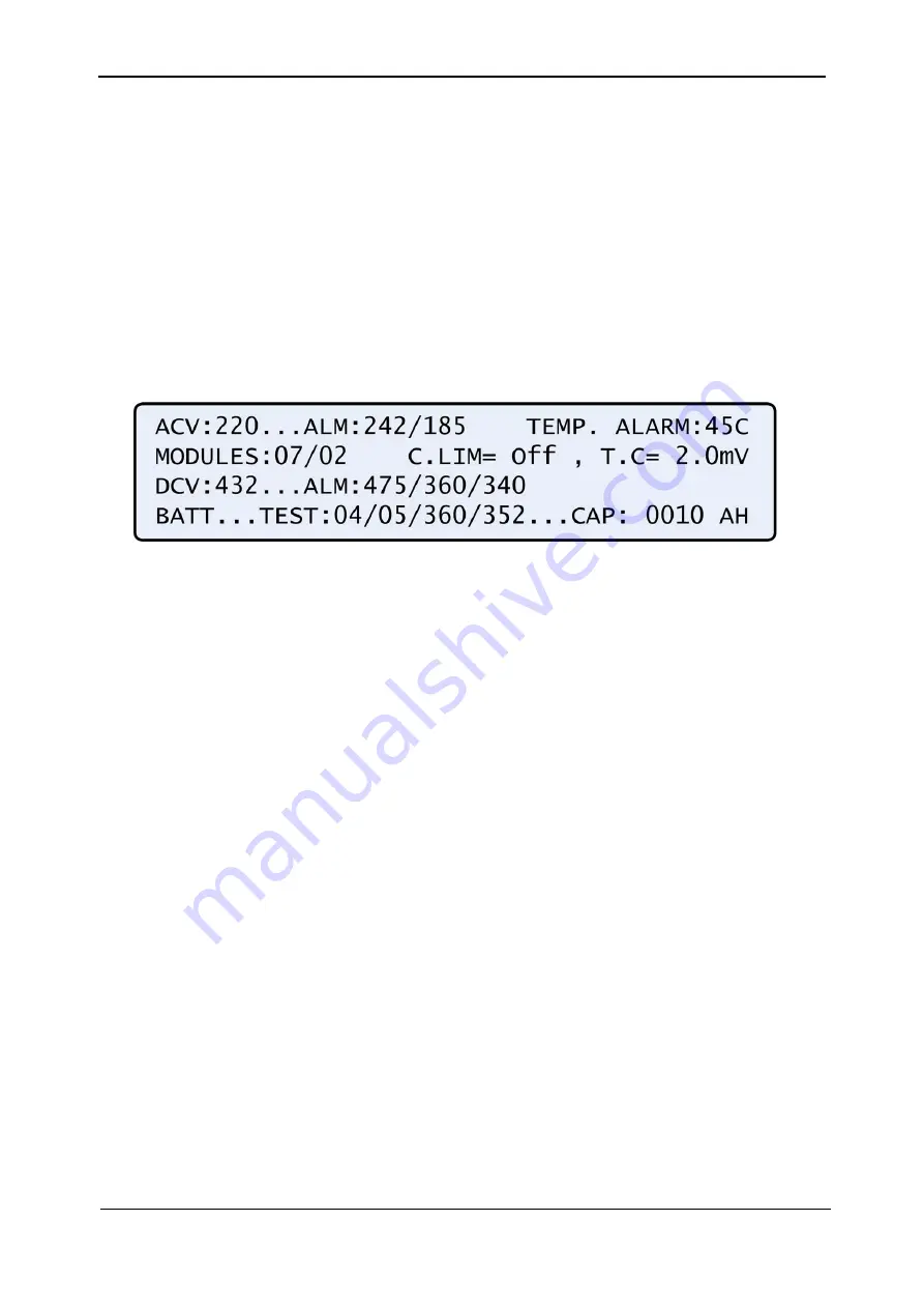
11.4.2 SCREEN 1
a) ACV: nominal value of the input/output AC voltage (220 for 2x32 batteries ; 110 for 2x16
batteries)
b) ALM: input AC voltage alarm HIGH/LOW
c) TEMP.ALARM: high temperature limit for external thermosensor
d) MODULES:
QUANTITY/REDUNDANCY
–
07/02 in the screen means that 7 modules are
presented in the system, 2 modules are reserve (full load is 10KVA*(7-2)=50KVA/40KW)
e) C.LIM.=off (VALUE)- battery current limit function is de-activated (off) or max. battery current
value in Amps. In C.LIM is activated, the system must be equipped with optional battery current
sensor.
f) T.C.=2.0mV
–
negative temperature coefficient of the battery DC voltage in mV per
º
C per
battery cell. Nominal temperature is 25
º
C. For DC nominal voltage 432V , temperature 35
º
C, 32
batteries of 6 cells, T.C.=2mV, the voltage is 432- 2*6*32*(35-25)~=428V. NOTE. For most
applications T.C. must be 0 (off).
g) DCV: DC nominal voltage for both positive and negative battery sets. For 32 batteries in the set
DCV=432V, for 16 batteries 216V.
h) DCV
…
ALM: DC voltage alarms HIGH/LOW/SHUTDOWN. SHUTDOWN alarm is DC voltage
value when the unit is stopped due to battery discharge.
i) BATT
…
.TEST: PERIOD IN WEEKS/MAX.DURATION IN HOURS/ALARM
VOLTAGE/CHARGER DERATED VOLTAGE. In the screen: the test is performed automatically
once per 4 weeks, max. test duration is 5 Hours, if battery voltage drops below 360V alarm
Battery Low is given, the chargers of the modules continue to supply voltage 352V to prevent
shutdown if battery is faulty.
j) CAP: CAPACITY in Amp-Hours. Is used to calculate estimated back up time of the system and
battery test duration.
Содержание POWER PLUS
Страница 13: ...Gamatronic Electronic Industries Ltd Power Technical Guide 5 Figure 2 2 Block diagram of a single UPS Module...
Страница 19: ...Gamatronic Electronic Industries Ltd Power Technical Guide 11 Figure 2 8 System controller Block diagram...
Страница 26: ...Gamatronic Electronic Industries Ltd 18 Power Technical Guide Figure 3 4 POWER System Rear View...


