Gamatronic Electronic Industries Ltd.
76
Power+ Technical Guide
9. TROUBLESHOOTING
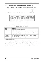
The system log (option "4 – HISTORY" on the main menu) can be very useful in determining the cause
of a UPS malfunction. See section
5.4 "Retrieving History (LOG of Events)" on page 62.
The indicator lights on the UPS module's front panel can also signal a malfunction.
Figure
9-1: UPS module front panel
9-1 there are three LEDs on the front panel of each UPS module: Alarm,
Output and Line. The internal buzzer in the UPS module sounds when there is no
communication with the system controller.
These 3 LEDs and the buzzer indicate the status of the UPS module (see Table
The alarm LED is red, line and output LEDs are green.
Normal condition is indicated by the green line LED and output LED on, with no beeps from the
buzzer.
Содержание POWER PLUS
Страница 13: ...Gamatronic Electronic Industries Ltd Power Technical Guide 5 Figure 2 2 Block diagram of a single UPS Module...
Страница 19: ...Gamatronic Electronic Industries Ltd Power Technical Guide 11 Figure 2 8 System controller Block diagram...
Страница 26: ...Gamatronic Electronic Industries Ltd 18 Power Technical Guide Figure 3 4 POWER System Rear View...


