Gamatronic Electronic Industries Ltd.
36
Power+ Technical Guide
3.8
SETTING THE SHELF ADDRESS
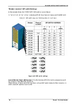
Each UPS module shelf – including the controller module shelf – has a digital address that can
be accessed by the module once it has been initialized. The module addresses are used to
identify each module during the normal operation and monitoring of the system.
No two shelves can have the same address. The address is related to the physical location of a
specific shelf, and is preset at the factory by the
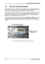
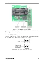
“Module Location” DIP switch
mounted on
the control PCB. (See Figure
3-26). When adding a new module to an existing system, the
address of the newly added shelf must be set correctly.
The control PCB contains an additional DIP switch – the
“Master/Slave” DIP switch
– that is
used to indicate which of the UPS modules is the “Master”, and which UPS modules are the
“Slaves”. Only one UPS module is designated as “Master”; all of the other UPS modules are
“Slaves”.
Figure
3-26: The PC917 Control PCB on a shelf – general view
Содержание POWER PLUS
Страница 13: ...Gamatronic Electronic Industries Ltd Power Technical Guide 5 Figure 2 2 Block diagram of a single UPS Module...
Страница 19: ...Gamatronic Electronic Industries Ltd Power Technical Guide 11 Figure 2 8 System controller Block diagram...
Страница 26: ...Gamatronic Electronic Industries Ltd 18 Power Technical Guide Figure 3 4 POWER System Rear View...

