Gamatronic Electronic Industries Ltd.
Power+ Technical Guide
41
A. This unit features advanced rectifier technology which allows you to connect triple phase voltage to
the inputs or just a single phase linked together on R (L1), S (L2) and T (L3) inputs. The unit will accept
both connection types on the input, no additional settings are needed.
3.9.2.5 Q:
H
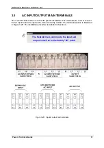
OW CAN THIS SYSTEM WORK AS A SINGLE AND TRIPLE PHASE
(
SELECTABLE
)
ON THE OUTPUT
?
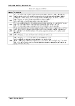
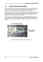
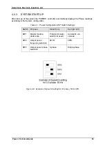
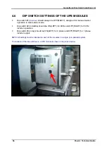
A. The special inverter function allows single phase output operation. To switch the system to single
phase operation, each UPS module should be removed while the system is off and its dip switch number
3 (they are located in a small window on the left side of each module) should be moved to the OFF
position (ON for 3 phase output operation). Then the output phases R (L1), S (L2) and T (L3) should be
linked altogether to a single phase wire output (used with the output neutral), as the phase angle will be
switched to 0
0
and each module will have its inverters operating in parallel.
3.9.2.6 Q:
H
OW CAN THIS SYSTEM BE SWITCHED TO
60H
Z OUTPUT
?
A. The unit will auto-detect input frequency and have same frequency on the output. To switch the
system to 60Hz output operation manually, each UPS module should be removed while the system is off
and its dip switch number 2 (they are located in a small window on the left side of each module) should
be moved to the on position (off for 50 Hz or auto-detect output operation).
3.9.2.7 Q:
H
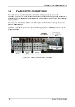
OW WILL THE
ST/SW
MODULE REACT TO A CHANGE FROM TRIPLE TO
SINGLE PHASE AND VICE VERSA ON THE OUTPUT
?
A. The bypass input of the unit should fit the output voltage. If the output voltage is triple phase, then the
bypass input should be triple phase as well. If the output is single phase, and the output phases are
linked altogether, then the same thing should be done with the bypass input of the unit
–
one phase
connected and the R (L1), S (L2) and the T (L3) inputs of the bypass linked altogether. The ST/SW
module will detect it and function as a triple or single phase unit automatically.
3.9.2.8 Q:
D
OES THIS UNIT HAVE DRY CONTACT OUTPUTS
,
AND FOR WHAT ALARMS
?
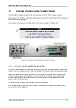
A. These systems have 6 dry contacts on the controller
’
s rear panel. Two of them are in a DB9
connector (pins 3, 4 alarm no. 1 and pins 5, 4 alarm no. 2). The other four are located in a marked wide
green connector with screw wire attachments. There are N.O., N.C. and the COMMON connections for
each dry contact. All dry contacts are programmable through the controller, selectable from the global list
of 32 alarms. Any number of alarms can be set for any dry contact. All the contacts are rated at 24V 1A.
3.9.2.9 Q:
D
OES THIS UNIT HAVE INPUT DRY CONTACTS
?
A. There are 4 input normally closed dry contacts, located in specific green plug on the rear side of the
system controller. As a standard they are all linked to the common on the plug, and provide no alarms.
3.9.3 MENUS
3.9.3.1 Q:
W
HAT IS THE ALARM
“
HYSTERESIS
”
SETTING
?
A. The voltage alarm hysteresis is the value of voltage difference for finalizing the alarm. For example, if
the alarm value is 245v and the hysteresis is 5v, then when the voltage grows above 245v and the alarm
will activate, it will end only when the voltage drops below 240v.
3.9.3.2 Q:
W
HAT IS THE
“I
NTEGRAT
.”
MENU ENTRY
?
A. The
“
Integrat.
”
, which is the integration factor, is a value for confirming the internal RS232
communications. This option should not be changed usually and is preset for optimal performance.
Содержание POWER PLUS
Страница 13: ...Gamatronic Electronic Industries Ltd Power Technical Guide 5 Figure 2 2 Block diagram of a single UPS Module...
Страница 19: ...Gamatronic Electronic Industries Ltd Power Technical Guide 11 Figure 2 8 System controller Block diagram...
Страница 26: ...Gamatronic Electronic Industries Ltd 18 Power Technical Guide Figure 3 4 POWER System Rear View...

